2023 Advanced Higher Physics questions
Source: Scottish Qualifications Authority (SQA) / Qualifications Scotland. This is a StemInteract HTML companion, not an official HTML edition. Selectable text is supplied alongside original page images. Use the images or original PDF for equations, powers, fractions, vector notation, tables and diagrams; text extraction cannot fully preserve mathematical layout.
Jump to a question
PDF page 1
Selectable page text
FOR OFFICIAL USE
AH
National
Qualications
Mark
2023
X857/77/01 Physics
WEDNESDAY, 17 MAY
9:00 AM – 12:00 NOON
*X8577701*
Fill in these boxes and read what is printed below.
Full name of centre Town
Forename(s) Surname Number of seat
Date of birth
Day Month Year Scottish candidate number
Total marks — 155
Attempt ALL questions.
Reference may be made to the Physics relationships sheet X857/77/11 and the data sheet on
page 02.
Write your answers clearly in the spaces provided in this booklet. Additional space for answers
and rough work is provided at the end of this booklet. If you use this space you must clearly
identify the question number you are attempting. Any rough work must be written in this
booklet. You should score through your rough work when you have written your final copy.
Care should be taken to give an appropriate number of significant figures in the final answers to
calculations.
Use blue or black ink.
Before leaving the examination room you must give this booklet to the Invigilator; if you do not,
you may lose all the marks for this paper.
©
*X857770101*
A/PBPDF page 2
Selectable page text
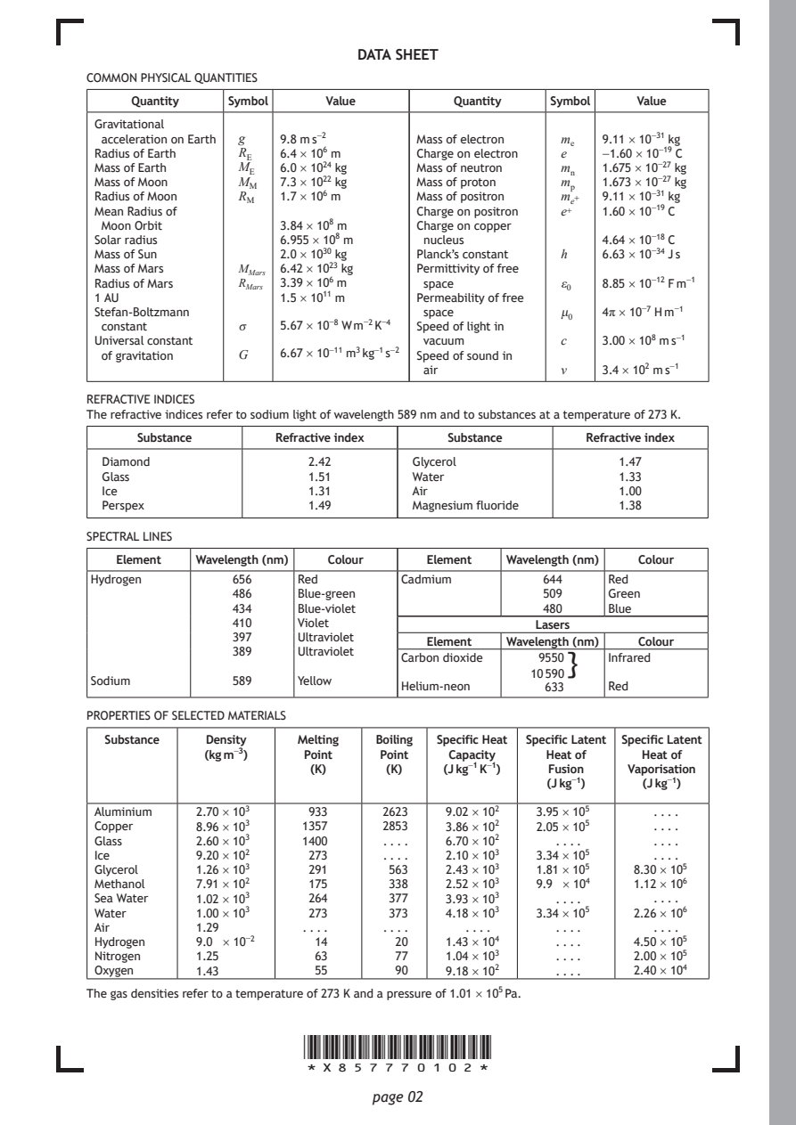
DATA SHEET
COMMON PHYSICAL QUANTITIES

     Quantity  Symbol    Value        Quantity  Symbol   Value
 Gravitational
 acceleration on Earth g 9.8 m s⁻² Mass of electron mₑ 9.11 × 10⁻³¹ kg
 Radius of Earth R_{E} 6.4 × 10⁶ m Charge on electron e −1.60 × 10⁻¹⁹ C
 Mass of Earth  M_{E} 6.0 × 10²⁴ kg Mass of neutron mₙ 1.675 × 10⁻²⁷ kg
 Mass of Moon   M_{M} 7.3 × 10²² kg Mass of proton mₚ 1.673 × 10⁻²⁷ kg
 Radius of Moon R_{M} 1.7 × 10⁶ m Mass of positron mₑ⁺ 9.11 × 10⁻³¹ kg
 Mean Radius of                   Charge on positron e⁺ 1.60 × 10⁻¹⁹ C
 Moon Orbit         3.84 × 10⁸ m  Charge on copper
 Solar radius       6.955 × 10⁸ m  nucleus           4.64 × 10⁻¹⁸ C
 Mass of Sun        2.0 × 10³⁰ kg Planck’s constant h 6.63 × 10⁻³⁴ J s
 Mass of Mars   M_{M}ₐᵣₛ 6.42 × 10²³ kg Permittivity of free
 Radius of Mars R_{M}ₐᵣₛ 3.39 × 10⁶ m space      ε₀  8.85 × 10⁻¹² F m⁻¹
 1 AU               1.5 × 10¹¹ m  Permeability of free
 Stefan-Boltzmann                  space         μ₀  4π × 10⁻⁷ H m⁻¹
 constant       σ   5.67 × 10⁻⁸ W m⁻² K⁻⁴ Speed of light in
 Universal constant                vacuum        c   3.00 × 10⁸ m s⁻¹
 of gravitation G   6.67 × 10⁻¹¹ m³ kg⁻¹ s⁻² Speed of sound in
                                   air           v   3.4 × 10² m s⁻¹
REFRACTIVE INDICES
The refractive indices refer to sodium light of wavelength 589 nm and to substances at a temperature of 273 K.
     Substance     Refractive index  Substance     Refractive index
  Diamond              2.42       Glycerol             1.47
  Glass                1.51       Water                1.33
  Ice                  1.31       Air                  1.00
  Perspex              1.49       Magnesium fluoride   1.38
SPECTRAL LINES
   Element Wavelength (nm) Colour  Element Wavelength (nm) Colour
Hydrogen       656    Red       Cadmium        644    Red
               486    Blue-green               509    Green
               434    Blue-violet              480    Blue
               410    Violet                  Lasers
               397    Ultraviolet
                                   Element Wavelength (nm) Colour
               389    Ultraviolet
                                Carbon dioxide 9550}  Infrared
                                              10 590
Sodium         589    Yellow
                                Helium-neon    633    Red
PROPERTIES OF SELECTED MATERIALS
  Substance Density   Melting Boiling Specific Heat Specific Latent Specific Latent
            (kg m⁻³)  Point   Point  Capacity  Heat of   Heat of
                       (K)     (K)   (J kg⁻¹ K⁻¹) Fusion Vaporisation
                                               (J kg⁻¹)  (J kg⁻¹)
 Aluminium 2.70 × 10³  933    2623   9.02 × 10² 3.95 × 10⁵ . . . .
 Copper    8.96 × 10³ 1357    2853   3.86 × 10² 2.05 × 10⁵ . . . .
 Glass     2.60 × 10³ 1400     . . . . 6.70 × 10² . . . . . . . .
 Ice       9.20 × 10²  273     . . . . 2.10 × 10³ 3.34 × 10⁵ . . . .
 Glycerol  1.26 × 10³  291     563   2.43 × 10³ 1.81 × 10⁵ 8.30 × 10⁵
 Methanol  7.91 × 10²  175     338   2.52 × 10³ 9.9 × 10⁴ 1.12 × 10⁶
 Sea Water 1.02 × 10³  264     377   3.93 × 10³ . . . .   . . . .
 Water     1.00 × 10³  273     373   4.18 × 10³ 3.34 × 10⁵ 2.26 × 10⁶
 Air       1.29       . . . .  . . . . . . . .  . . . .   . . . .
 Hydrogen  9.0 × 10⁻²  14       20   1.43 × 10⁴ . . . . 4.50 × 10⁵
 Nitrogen  1.25        63       77   1.04 × 10³ . . . . 2.00 × 10⁵
 Oxygen    1.43        55       90   9.18 × 10² . . . . 2.40 × 10⁴
The gas densities refer to a temperature of 273 K and a pressure of 1.01 × 10⁵ Pa.
                      *X857770102*
                             page 02
PDF page 3

Selectable page text
[Turn over for next question

DO NOT WRITE ON THIS PAGE

*X857770103*

       page 03
PDF page 4
Question 1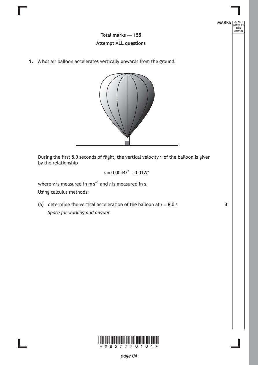
Selectable page text
MARKS _{W}^{D}_{R}^{O}_{I} _{T}^{N}OT
                                                                   E IN
                                                                  THIS
                                                                 MARGIN
                       Total marks — 155
                      Attempt ALL questions

1. A hot air balloon accelerates vertically upwards from the ground.

   During the first 8.0 seconds of flight, the vertical velocity v of the balloon is given
   by the relationship
                        v=0.0044t³ +0.012t²

   where v is measured in m s⁻¹ and t is measured in s.

   Using calculus methods:

   (a) determine the vertical acceleration of the balloon at t = 8.0 s 3
      Space for working and answer

                      *X857770104*

                             page 04
PDF page 5
Selectable page text
MARKS _{W}^{D}_{R}^{O}_{I} _{T}^{N}OT
                                                                   E IN
                                                                  THIS
                                                                 MARGIN
1. (continued)
   (b) determine the vertical displacement of the balloon at t = 8.0 s. 3
      Space for working and answer

                                                     [Turn over

                      *X857770105*

                             page 05
PDF page 6
Question 2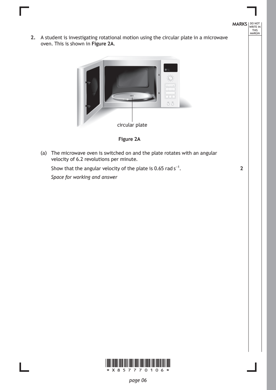
Selectable page text
MARKS _{W}^{D}_{R}^{O}_{I} _{T}^{N}OT
                                                                   E IN
                                                                  THIS
                                                                 MARGIN
2. A student is investigating rotational motion using the circular plate in a microwave
   oven. This is shown in Figure 2A.

                          circular plate

                          Figure 2A

   (a) The microwave oven is switched on and the plate rotates with an angular
      velocity of 6.2 revolutions per minute.

      Show that the angular velocity of the plate is 0.65 rad s⁻¹. 2
      Space for working and answer

                      *X857770106*

                             page 06
PDF page 7
Selectable page text
MARKS _{W}^{D}_{R}^{O}_{I} _{T}^{N}OT
                                                                   E IN
                                                                  THIS
                                                                 MARGIN
2. (continued)
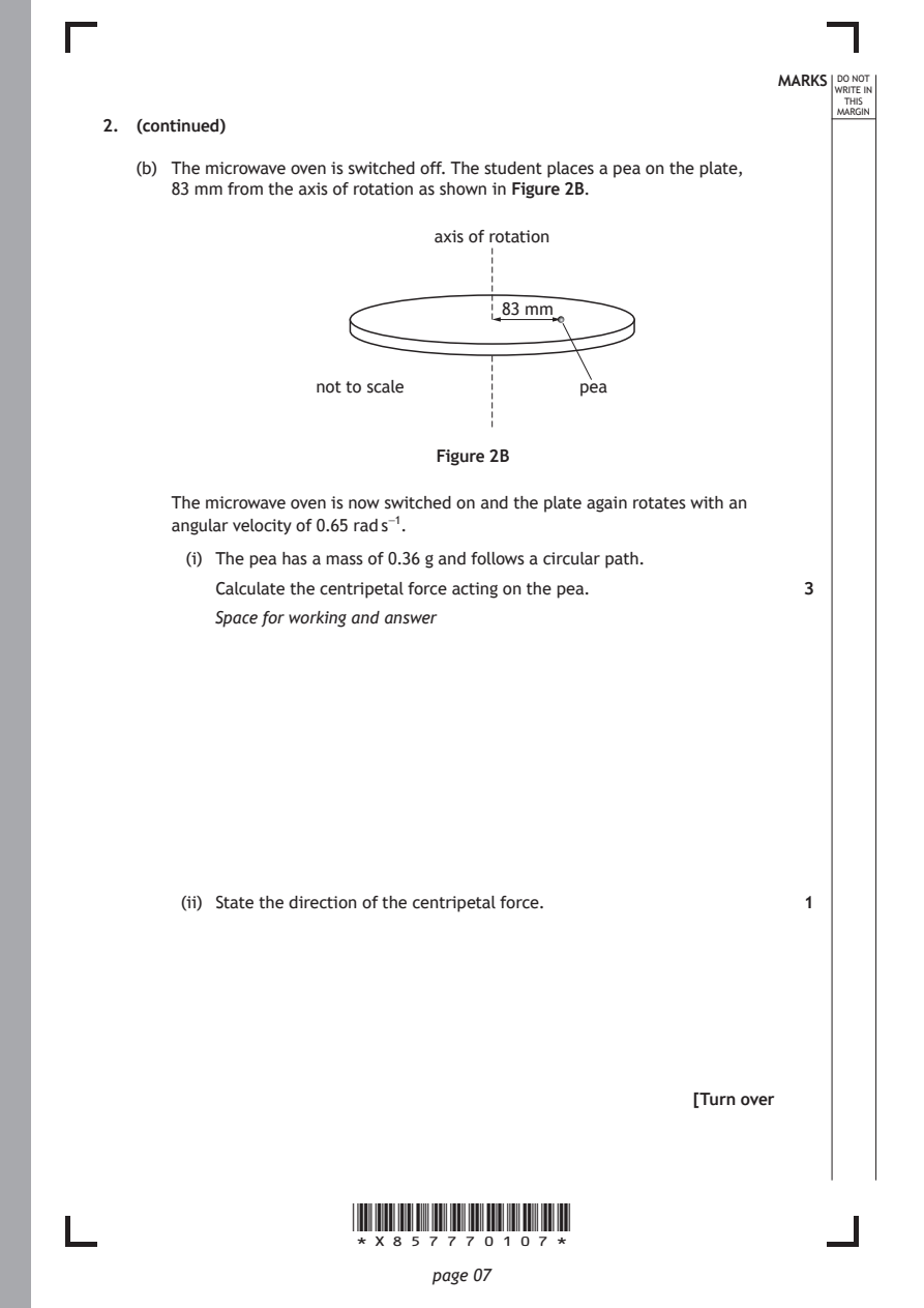
   (b) The microwave oven is switched off. The student places a pea on the plate,
      83 mm from the axis of rotation as shown in Figure 2B.
                              axis of rotation

                                    83 mm

                   not to scale            pea

                              Figure 2B

      The microwave oven is now switched on and the plate again rotates with an
      angular velocity of 0.65 rad s⁻¹.
        (i) The pea has a mass of 0.36 g and follows a circular path.

          Calculate the centripetal force acting on the pea.  3
          Space for working and answer

       (ii) State the direction of the centripetal force.     1

                                                     [Turn over

                      *X857770107*

                             page 07
PDF page 8
Selectable page text
MARKS _{W}^{D}_{R}^{O}_{I} _{T}^{N}OT
                                                                   E IN
                                                                  THIS
                                                                 MARGIN
2. (continued)
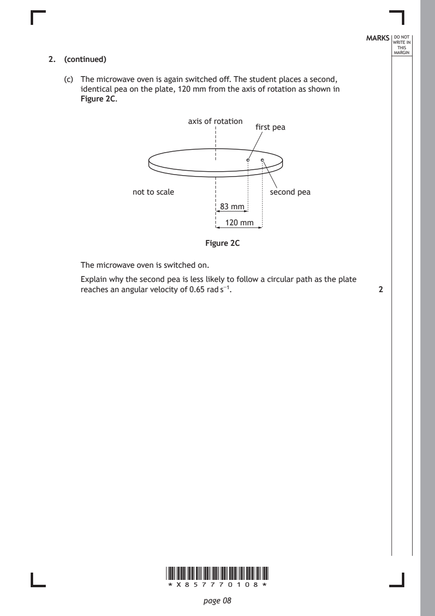
   (c) The microwave oven is again switched off. The student places a second,
      identical pea on the plate, 120 mm from the axis of rotation as shown in
      Figure 2C.
                           axis of rotation
                                       first pea

                not to scale              second pea
                                 83 mm

                                  120 mm

                              Figure 2C

      The microwave oven is switched on.
      Explain why the second pea is less likely to follow a circular path as the plate
      reaches an angular velocity of 0.65 rad s⁻¹.            2

                      *X857770108*

                             page 08
PDF page 9
Question 3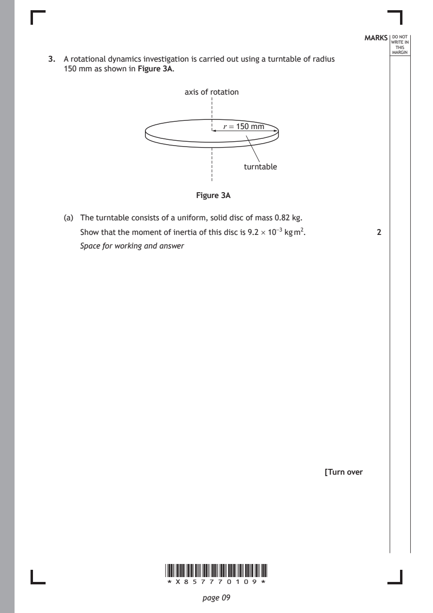
Selectable page text
MARKS _{W}^{D}_{R}^{O}_{I} _{T}^{N}OT
                                                                   E IN
                                                                  THIS
                                                                 MARGIN
3. A rotational dynamics investigation is carried out using a turntable of radius
   150 mm as shown in Figure 3A.
                          axis of rotation

                                 r = 150 mm

                                     turntable

                            Figure 3A

   (a) The turntable consists of a uniform, solid disc of mass 0.82 kg.
      Show that the moment of inertia of this disc is 9.2 × 10⁻³ kg m². 2

      Space for working and answer

                                                     [Turn over

                      *X857770109*

                             page 09
PDF page 10
Selectable page text
MARKS _{W}^{D}_{R}^{O}_{I} _{T}^{N}OT
                                                                   E IN
                                                                  THIS
                                                                 MARGIN
3. (continued)
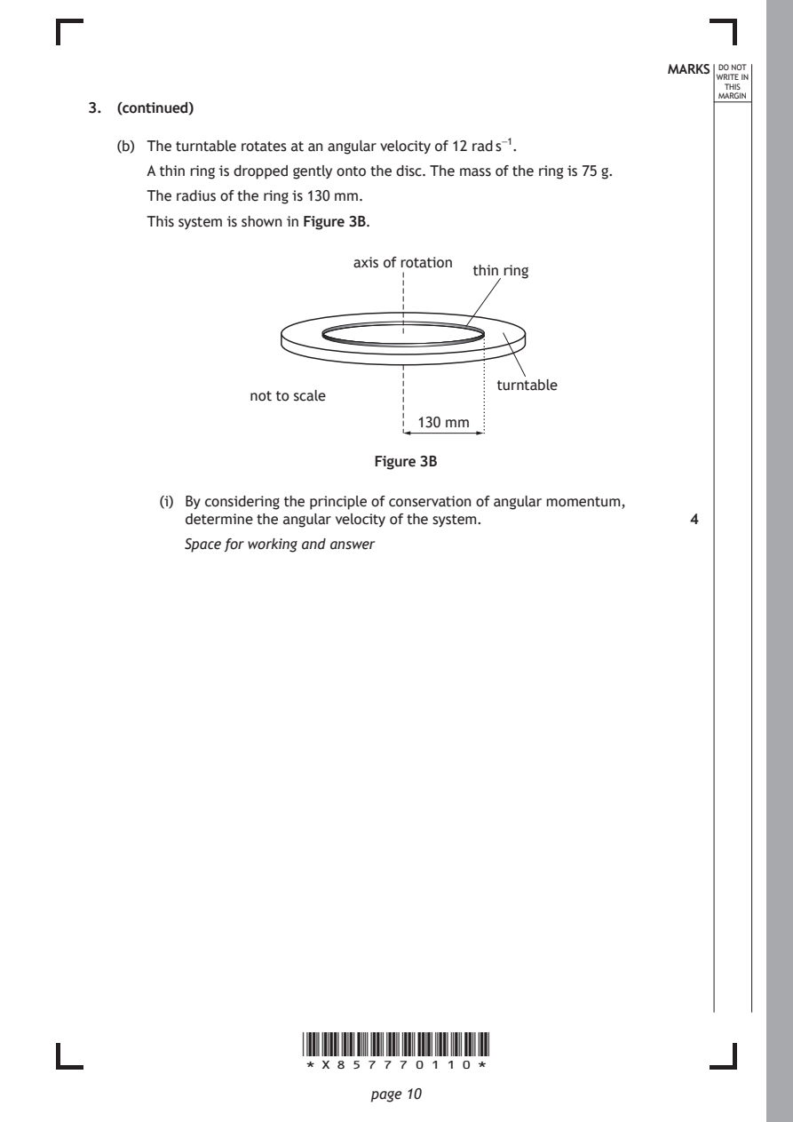
   (b) The turntable rotates at an angular velocity of 12 rad s⁻¹.
      A thin ring is dropped gently onto the disc. The mass of the ring is 75 g.
      The radius of the ring is 130 mm.
      This system is shown in Figure 3B.

                            axis of rotation
                                        thin ring

                                          turntable
                 not to scale
                                  130 mm

                              Figure 3B

        (i) By considering the principle of conservation of angular momentum,
          determine the angular velocity of the system.       4
          Space for working and answer

                      *X857770110*

                             page 10
PDF page 11
Selectable page text
MARKS _{W}^{D}_{R}^{O}_{I} _{T}^{N}OT
                                                                   E IN
                                                                  THIS
                                                                 MARGIN
3. (b) (continued)
       (ii) Determine the loss in rotational kinetic energy due to the interaction
          between the ring and the turntable.                 4
          Space for working and answer

       (iii) During the interaction some rotational kinetic energy is converted into
          heat.
          Explain how this heat is generated.                 1

                                                     [Turn over

                      *X857770111*

                             page 11
PDF page 12
Question 4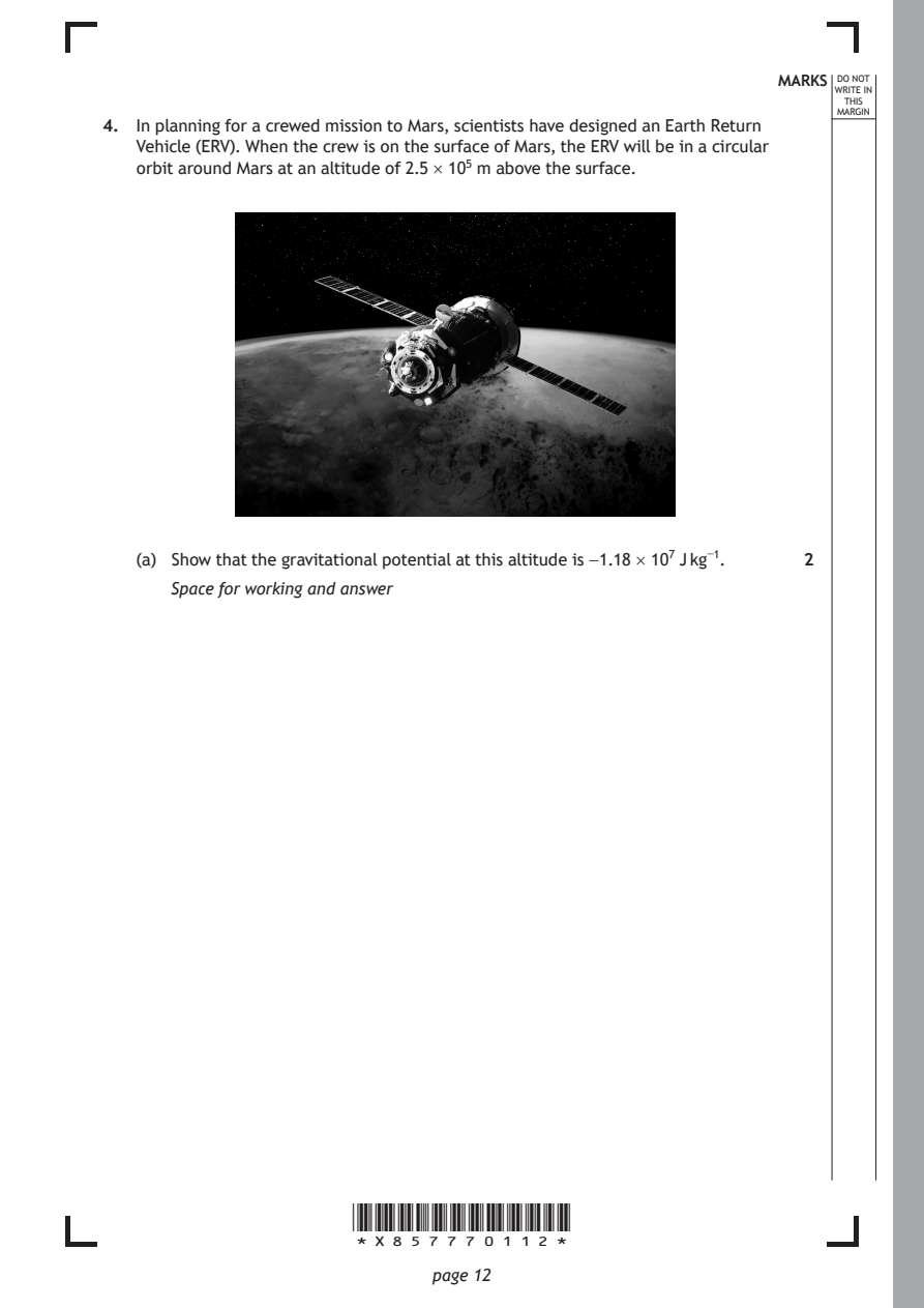
Selectable page text
MARKS _{W}^{D}_{R}^{O}_{I} _{T}^{N}OT
                                                                   E IN
                                                                  THIS
                                                                 MARGIN
4. In planning for a crewed mission to Mars, scientists have designed an Earth Return
   Vehicle (ERV). When the crew is on the surface of Mars, the ERV will be in a circular
   orbit around Mars at an altitude of 2.5 × 10⁵ m above the surface.

   (a) Show that the gravitational potential at this altitude is −1.18 × 10⁷ J kg⁻¹. 2

      Space for working and answer

                      *X857770112*

                             page 12
PDF page 13
Selectable page text
MARKS _{W}^{D}_{R}^{O}_{I} _{T}^{N}OT
                                                                   E IN
                                                                  THIS
                                                                 MARGIN
4. (continued)
   (b) The ERV will then move into a higher circular orbit. The gravitational potential
      at the higher orbit is −1.10 × 10⁷ J kg⁻¹.
      The ERV will have a mass of 4.3 × 10³ kg.
      Determine the change in gravitational potential energy of the ERV when it has
      moved from the lower orbit to the higher orbit.         4

      Space for working and answer

                                                     [Turn over

                      *X857770113*

                             page 13
PDF page 14
Selectable page text
MARKS _{W}^{D}_{R}^{O}_{I} _{T}^{N}OT
                                                                   E IN
                                                                  THIS
                                                                 MARGIN
4. (continued)
   (c) Another spacecraft, the Mars Ascent Vehicle (MAV), will transport crew and
      cargo from the surface of Mars to the ERV.
        (i) Calculate the escape velocity from the surface of Mars. 3
          Space for working and answer

       (ii) The MAV will dock with the ERV in the higher circular orbit, at an altitude
          of 5.0 × 10⁵ m above the surface of Mars.

          Explain why the MAV does not have to attain the escape velocity
          calculated in (c) (i) to reach this altitude.       1

                      *X857770114*

                             page 14
PDF page 15
Selectable page text
MARKS _{W}^{D}_{R}^{O}_{I} _{T}^{N}OT
                                                                   E IN
                                                                  THIS
                                                                 MARGIN
4. (c) (continued)
       (iii) Calculate the tangential speed of the ERV in this orbit. 3
          Space for working and answer

       (iv) Suggest a reason why the docking manoeuvre will be easier to carry out
          at an altitude of 5.0 × 10⁵ m rather than at an altitude of 2.5 × 10⁵ m. 1

                                                     [Turn over

                      *X857770115*

                             page 15
PDF page 16
Question 5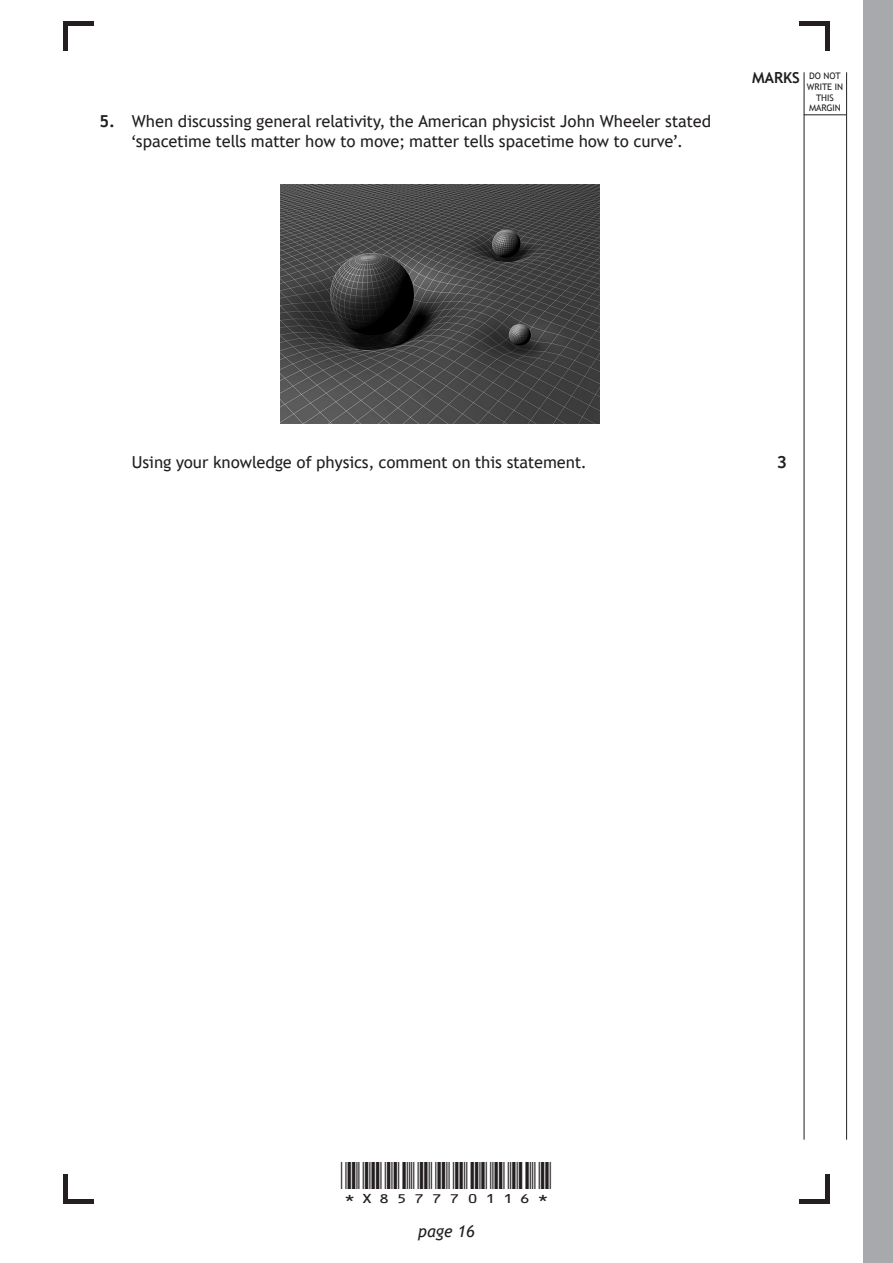
Selectable page text
MARKS _{W}^{D}_{R}^{O}_{I} _{T}^{N}OT
                                                                   E IN
                                                                  THIS
                                                                 MARGIN
5. When discussing general relativity, the American physicist John Wheeler stated
   ‘spacetime tells matter how to move; matter tells spacetime how to curve’.

   Using your knowledge of physics, comment on this statement. 3

                      *X857770116*

                             page 16
PDF page 17

Selectable page text
MARKS _{W}^{D}_{R}^{O}_{I} _{T}^{N}OT
                                                                   E IN
                                                                  THIS
                                                                 MARGIN
5. (continued)

                                                     [Turn over

                      *X857770117*

                             page 17
PDF page 18
Question 6
Selectable page text
MARKS _{W}^{D}_{R}^{O}_{I} _{T}^{N}OT
                                                                   E IN
                                                                  THIS
                                                                 MARGIN
6. The Sun is a main sequence star.
   (a) In the core of the Sun, energy is released when hydrogen is converted to
      helium in a series of nuclear fusion reactions.
      State the name given to this series of fusion reactions. 1

   (b) The Sun has a surface temperature of 5800 K.

        (i) Calculate the luminosity of the Sun.              3
          Space for working and answer

       (ii) State one assumption made in this calculation of luminosity. 1

                      *X857770118*

                             page 18
PDF page 19
Selectable page text
MARKS _{W}^{D}_{R}^{O}_{I} _{T}^{N}OT
                                                                   E IN
                                                                  THIS
                                                                 MARGIN
6. (continued)
   (c) When hydrogen fusion in its core stops, the Sun will leave the main sequence
      and become a red giant.
      Explain, in terms of thermal pressure and gravitational forces, what happens to
      the radius of the Sun as it becomes a red giant.        2

                                                     [Turn over

                      *X857770119*

                             page 19
PDF page 20
Selectable page text
MARKS _{W}^{D}_{R}^{O}_{I} _{T}^{N}OT
                                                                   E IN
                                                                  THIS
                                                                 MARGIN
6. (continued)
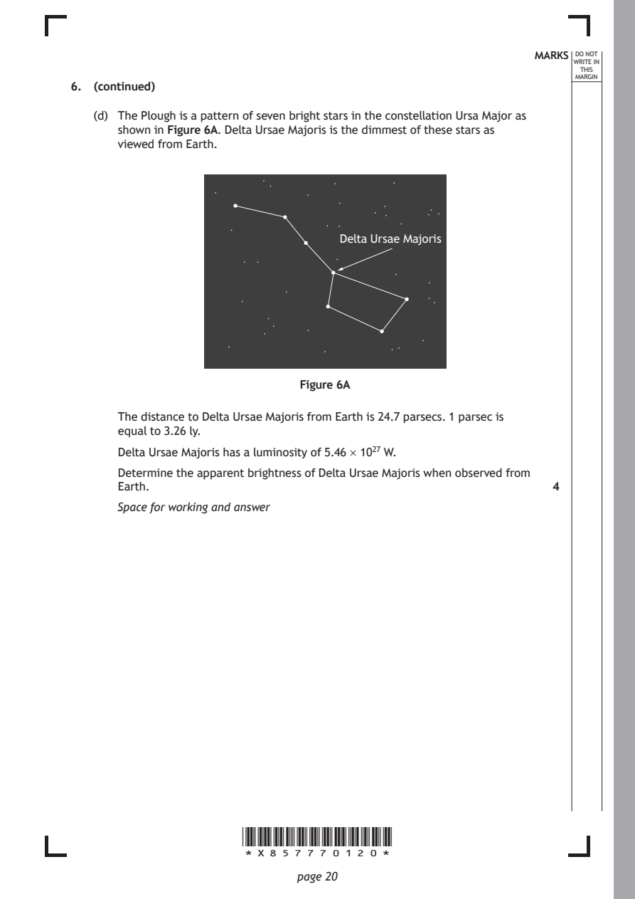
   (d) The Plough is a pattern of seven bright stars in the constellation Ursa Major as
      shown in Figure 6A. Delta Ursae Majoris is the dimmest of these stars as
      viewed from Earth.

                                   Delta Ursae Majoris

                              Figure 6A

      The distance to Delta Ursae Majoris from Earth is 24.7 parsecs. 1 parsec is
      equal to 3.26 ly.
      Delta Ursae Majoris has a luminosity of 5.46 × 10²⁷ W.

      Determine the apparent brightness of Delta Ursae Majoris when observed from
      Earth.                                                  4
      Space for working and answer

                      *X857770120*

                             page 20
PDF page 21
Selectable page text
6. (continued)

                                                            MARKS _{W}^{D}_{R}^{O}_{I} _{T}^{N}OT
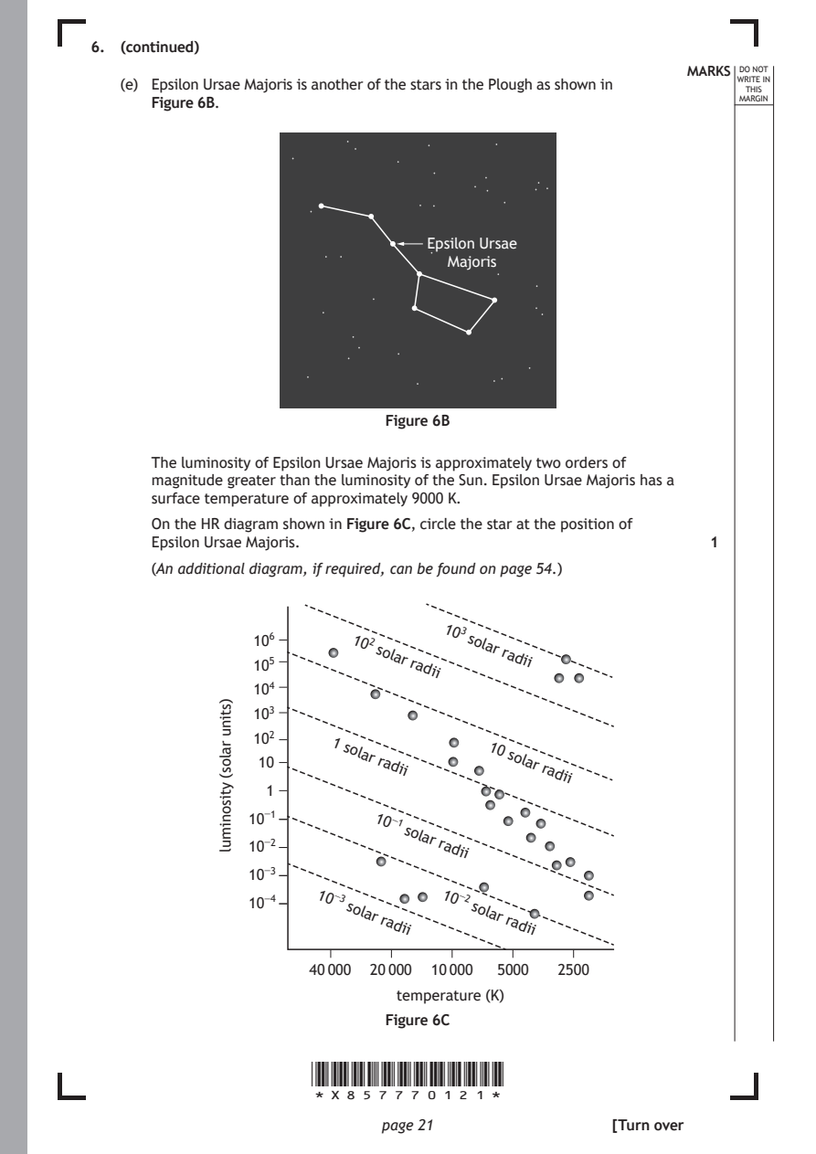
   (e) Epsilon Ursae Majoris is another of the stars in the Plough as shown in E IN
                                                                  THIS
      Figure 6B.                                                 MARGIN

                                  Epsilon Ursae
                                    Majoris

                              Figure 6B

      The luminosity of Epsilon Ursae Majoris is approximately two orders of
      magnitude greater than the luminosity of the Sun. Epsilon Ursae Majoris has a
      surface temperature of approximately 9000 K.
      On the HR diagram shown in Figure 6C, circle the star at the position of
      Epsilon Ursae Majoris.

      (An additional diagram, if required, can be found on page 54.)

                          102
                             solar
                                radii
                                   103
                                      solar
                                         radii
                        1
                         solar
                             radii
                                        10
                                          solar
                                             radii
                             10⁻¹
                               solar
                                   radii
                       10⁻³        10⁻²
                          solar
                             radii
                                      solar
                                          radii
                      40 000 20 000 10 000 5000 2500
                               temperature (K)

                      *X857770121*

                             page 21
             )stinu
             ralos(
             ytisonimul
                                                              1
                 10⁶
                 10⁵
                 10⁴
                 10³
                 10²
                 10
                  1
                10⁻¹
                10⁻²
                10⁻³
                10⁻⁴
                              Figure 6C
                                                     [Turn over
PDF page 22
Question 7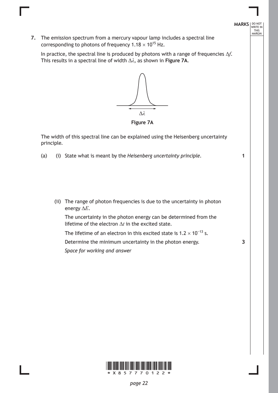
Selectable page text
MARKS _{W}^{D}_{R}^{O}_{I} _{T}^{N}OT
                                                                   E IN
                                                                  THIS
                                                                 MARGIN
7. The emission spectrum from a mercury vapour lamp includes a spectral line
   corresponding to photons of frequency 1.18 × 10¹⁵ Hz.
   In practice, the spectral line is produced by photons with a range of frequencies Δf.
   This results in a spectral line of width Δλ, as shown in Figure 7A.

                                Δλ

                              Figure 7A

   The width of this spectral line can be explained using the Heisenberg uncertainty
   principle.

   (a)  (i) State what is meant by the Heisenberg uncertainty principle. 1

       (ii) The range of photon frequencies is due to the uncertainty in photon
          energy ∆E.
          The uncertainty in the photon energy can be determined from the

          lifetime of the electron ∆t in the excited state.
          The lifetime of an electron in this excited state is 1.2 × 10⁻¹³ s.

          Determine the minimum uncertainty in the photon energy. 3
          Space for working and answer

                      *X857770122*

                             page 22
PDF page 23
Selectable page text
MARKS _{W}^{D}_{R}^{O}_{I} _{T}^{N}OT
                                                                   E IN
                                                                  THIS
                                                                 MARGIN
7. (a) (continued)
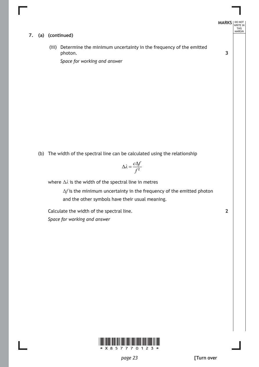
       (iii) Determine the minimum uncertainty in the frequency of the emitted
          photon.                                             3
          Space for working and answer

   (b) The width of the spectral line can be calculated using the relationship
                                 cΔf
                              Δλ=
                                  f ²

      where Δλ is the width of the spectral line in metres
           Δf is the minimum uncertainty in the frequency of the emitted photon

           and the other symbols have their usual meaning.

      Calculate the width of the spectral line.               2
      Space for working and answer

                      *X857770123*

                             page 23                 [Turn over
PDF page 24
Question 8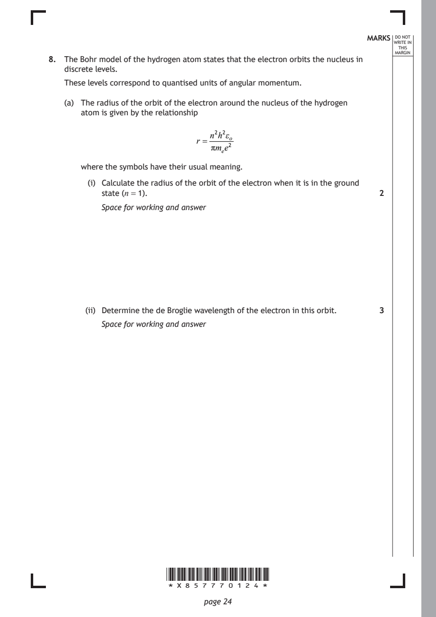
Selectable page text
MARKS _{W}^{D}_{R}^{O}_{I} _{T}^{N}OT
                                                                   E IN
                                                                  THIS
                                                                 MARGIN
8. The Bohr model of the hydrogen atom states that the electron orbits the nucleus in
   discrete levels.
   These levels correspond to quantised units of angular momentum.
   (a) The radius of the orbit of the electron around the nucleus of the hydrogen
      atom is given by the relationship

                               n²hε² _{ο}
                            r =
                               πmₑe²
      where the symbols have their usual meaning.

        (i) Calculate the radius of the orbit of the electron when it is in the ground
          state (n = 1).                                      2
          Space for working and answer

       (ii) Determine the de Broglie wavelength of the electron in this orbit. 3

          Space for working and answer

                      *X857770124*

                             page 24
PDF page 25
Selectable page text
MARKS _{W}^{D}_{R}^{O}_{I} _{T}^{N}OT
                                                                   E IN
                                                                  THIS
                                                                 MARGIN
8. (continued)
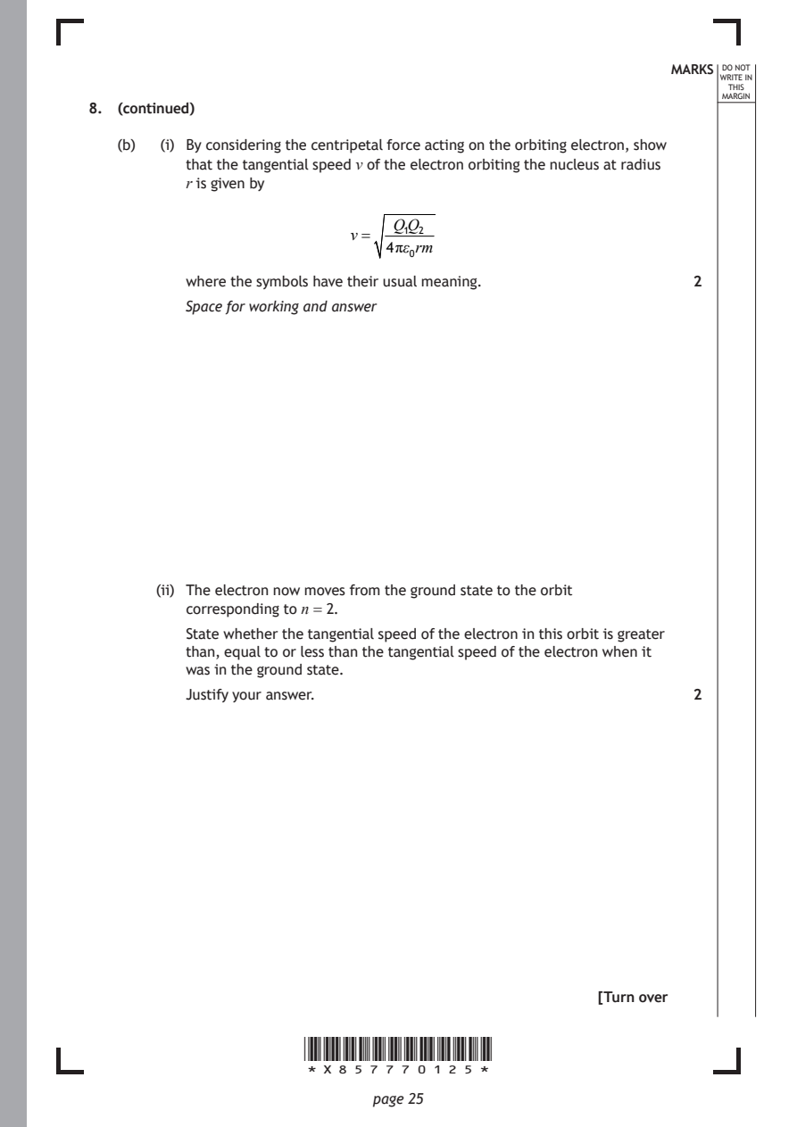
   (b)  (i) By considering the centripetal force acting on the orbiting electron, show
          that the tangential speed v of the electron orbiting the nucleus at radius
          r is given by

                                Q₁Q₂
                           v=
                               4πε₀rm
          where the symbols have their usual meaning.         2
          Space for working and answer

       (ii) The electron now moves from the ground state to the orbit
          corresponding to n = 2.
          State whether the tangential speed of the electron in this orbit is greater
          than, equal to or less than the tangential speed of the electron when it
          was in the ground state.

          Justify your answer.                                2

                                                     [Turn over

                      *X857770125*

                             page 25
PDF page 26
Question 9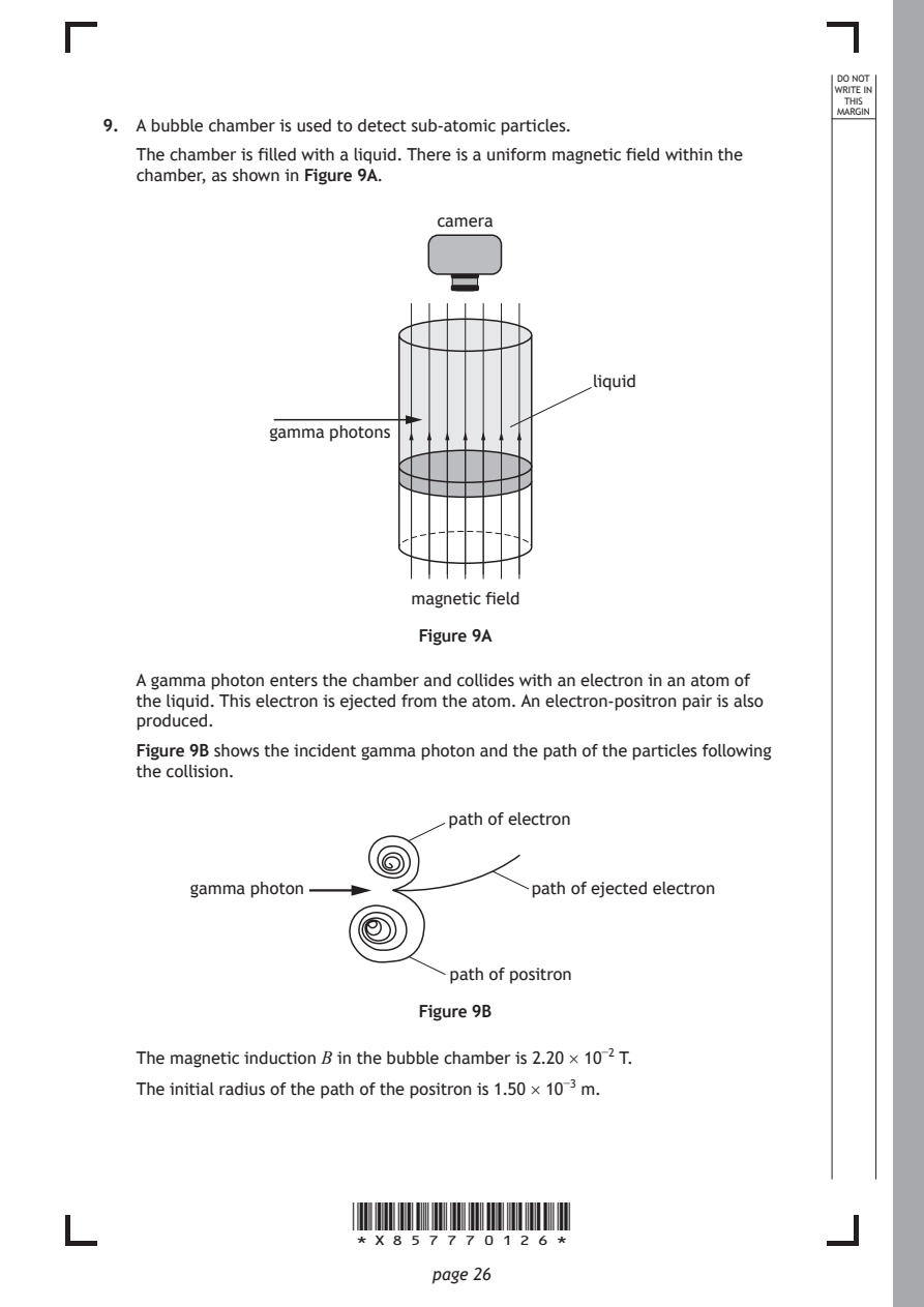
Selectable page text
DO NOT
                                                                 WRITE IN
                                                                  THIS
                                                                 MARGIN
9. A bubble chamber is used to detect sub-atomic particles.
   The chamber is filled with a liquid. There is a uniform magnetic field within the
   chamber, as shown in Figure 9A.
                              camera

                                            liquid

               gamma photons

                            magnetic field

                            Figure 9A

   A gamma photon enters the chamber and collides with an electron in an atom of
   the liquid. This electron is ejected from the atom. An electron-positron pair is also
   produced.

   Figure 9B shows the incident gamma photon and the path of the particles following
   the collision.

                               path of electron

        gamma photon                  path of ejected electron

                               path of positron

                            Figure 9B

   The magnetic induction B in the bubble chamber is 2.20 × 10⁻² T.

   The initial radius of the path of the positron is 1.50 × 10⁻³ m.

                      *X857770126*

                             page 26
PDF page 27
Selectable page text
MARKS _{W}^{D}_{R}^{O}_{I} _{T}^{N}OT
                                                                   E IN
                                                                  THIS
                                                                 MARGIN
9. (continued)
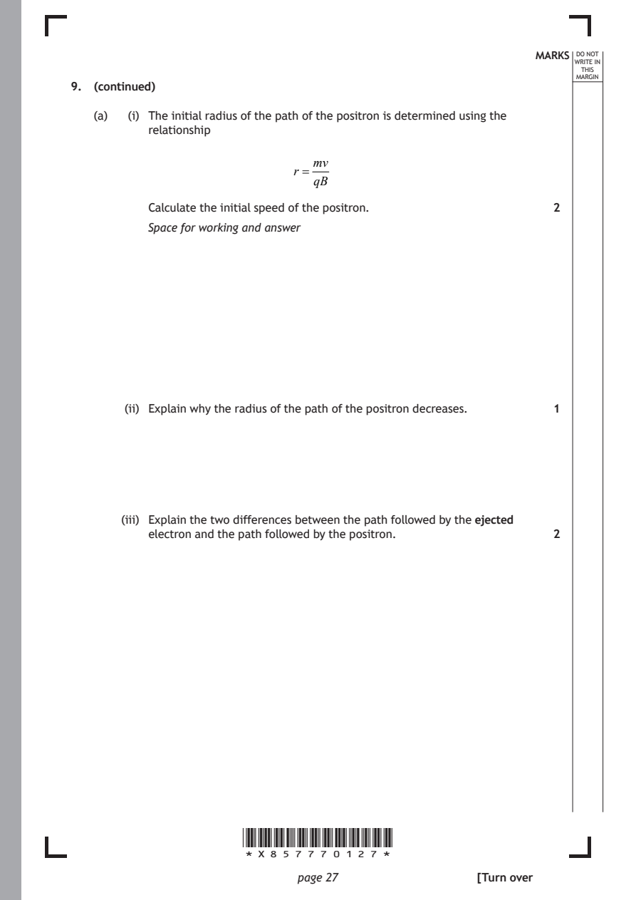
   (a)  (i) The initial radius of the path of the positron is determined using the
          relationship
                               mv
                             r =
                               qB

          Calculate the initial speed of the positron.        2
          Space for working and answer

       (ii) Explain why the radius of the path of the positron decreases. 1

       (iii) Explain the two differences between the path followed by the ejected
          electron and the path followed by the positron.     2

                      *X857770127*

                             page 27                 [Turn over
PDF page 28
Selectable page text
MARKS _{W}^{D}_{R}^{O}_{I} _{T}^{N}OT
                                                                   E IN
                                                                  THIS
                                                                 MARGIN
9. (continued)
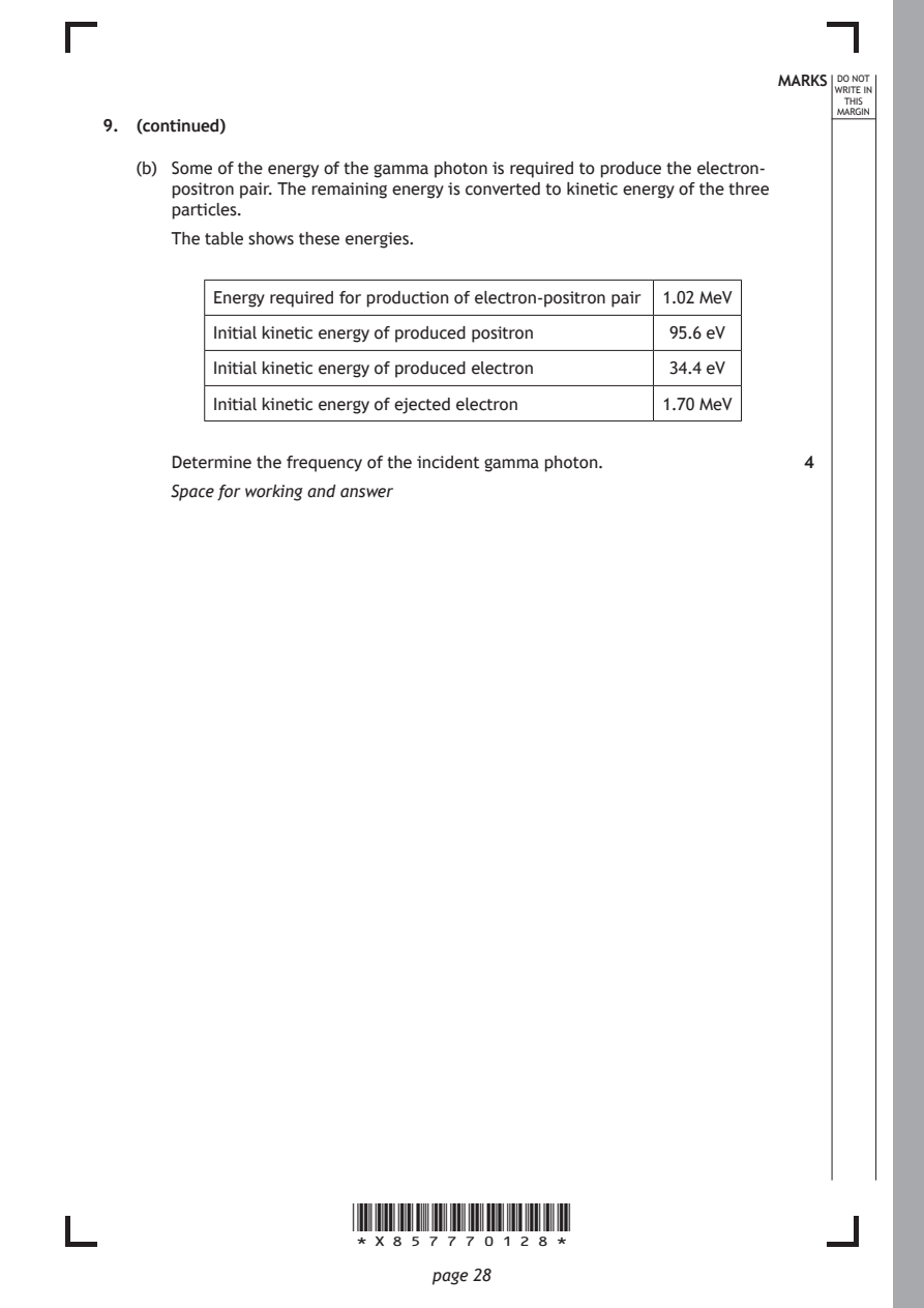
   (b) Some of the energy of the gamma photon is required to produce the electron-
      positron pair. The remaining energy is converted to kinetic energy of the three
      particles.
      The table shows these energies.

          Energy required for production of electron-positron pair 1.02 MeV

          Initial kinetic energy of produced positron 95.6 eV

          Initial kinetic energy of produced electron 34.4 eV

          Initial kinetic energy of ejected electron 1.70 MeV

      Determine the frequency of the incident gamma photon.   4
      Space for working and answer

                      *X857770128*

                             page 28
PDF page 29

Selectable page text
[Turn over for next question

DO NOT WRITE ON THIS PAGE

*X857770129*

       page 29
PDF page 30
Question 10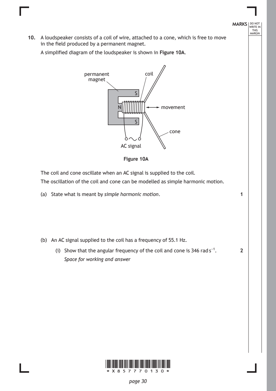
Selectable page text
MARKS _{W}^{D}_{R}^{O}_{I} _{T}^{N}OT
                                                                    E IN
                                                                   THIS
                                                                  MARGIN
10. A loudspeaker consists of a coil of wire, attached to a cone, which is free to move
    in the field produced by a permanent magnet.
    A simplified diagram of the loudspeaker is shown in Figure 10A.

                 permanent         coil
                  magnet

                                S

                           N            movement

                                S
                                          cone

                            AC signal

                             Figure 10A

    The coil and cone oscillate when an AC signal is supplied to the coil.

    The oscillation of the coil and cone can be modelled as simple harmonic motion.

    (a) State what is meant by simple harmonic motion.         1

    (b) An AC signal supplied to the coil has a frequency of 55.1 Hz.

         (i) Show that the angular frequency of the coil and cone is 346 rad s⁻¹. 2

           Space for working and answer

                       *X857770130*

                              page 30
PDF page 31
Selectable page text
MARKS _{W}^{D}_{R}^{O}_{I} _{T}^{N}OT
                                                                    E IN
                                                                   THIS
                                                                  MARGIN
10. (b) (continued)
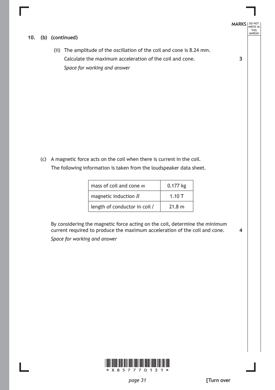
        (ii) The amplitude of the oscillation of the coil and cone is 8.24 mm.
           Calculate the maximum acceleration of the coil and cone. 3
           Space for working and answer

    (c) A magnetic force acts on the coil when there is current in the coil.

       The following information is taken from the loudspeaker data sheet.

                   mass of coil and cone m 0.177 kg

                   magnetic induction B    1.10 T

                   length of conductor in coil l 21.8 m

       By considering the magnetic force acting on the coil, determine the minimum
       current required to produce the maximum acceleration of the coil and cone. 4
       Space for working and answer

                       *X857770131*

                              page 31                 [Turn over
PDF page 32
Selectable page text
MARKS _{W}^{D}_{R}^{O}_{I} _{T}^{N}OT
E IN
THIS
MARGIN
10. (continued)
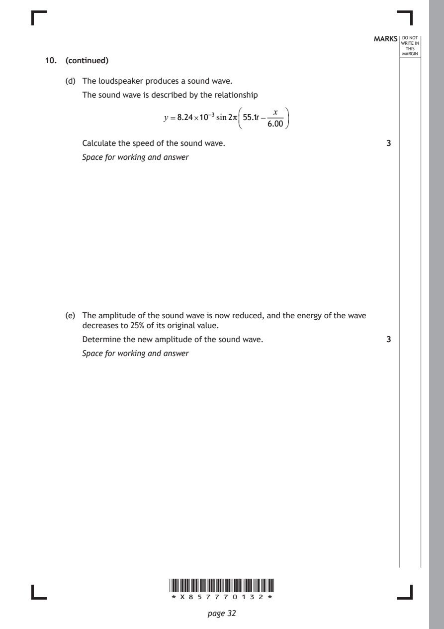
(d) The loudspeaker produces a sound wave.
The sound wave is described by the relationship
x
y =8.24×10⁻³sin2π55.1t−
6.00
Calculate the speed of the sound wave. 3
Space for working and answer
(e) The amplitude of the sound wave is now reduced, and the energy of the wave
decreases to 25% of its original value.
Determine the new amplitude of the sound wave. 3
Space for working and answer
*X857770132*
page 32PDF page 33
Selectable page text
MARKS _{W}^{D}_{R}^{O}_{I} _{T}^{N}OT
                                                                    E IN
                                                                   THIS
                                                                  MARGIN
10. (continued)
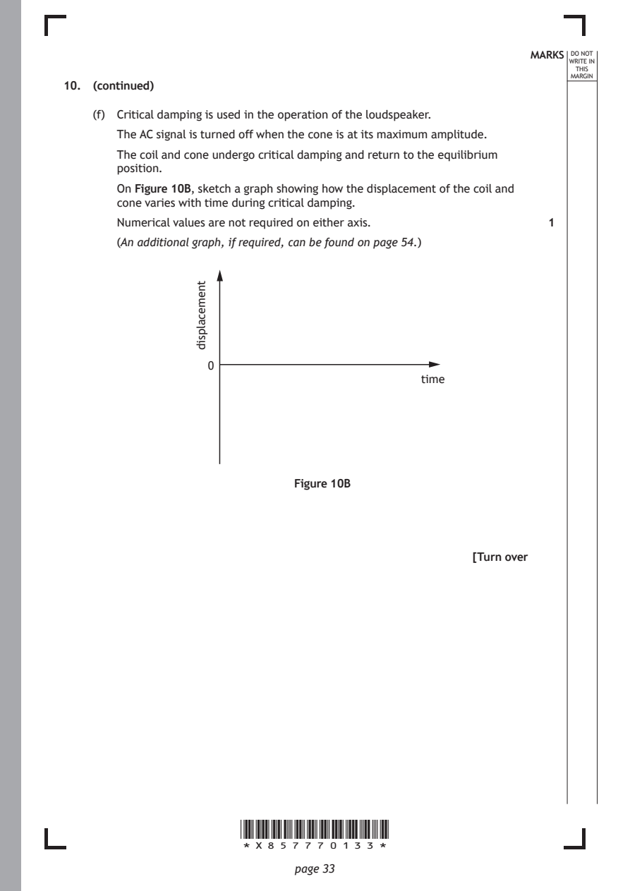
    (f) Critical damping is used in the operation of the loudspeaker.
       The AC signal is turned off when the cone is at its maximum amplitude.
       The coil and cone undergo critical damping and return to the equilibrium
       position.
       On Figure 10B, sketch a graph showing how the displacement of the coil and
       cone varies with time during critical damping.

       Numerical values are not required on either axis.
       (An additional graph, if required, can be found on page 54.)

                                               time

                       *X857770133*

                              page 33
                  tnemecalpsid
                                                               1
                   0
                              Figure 10B
                                                      [Turn over
PDF page 34
Question 11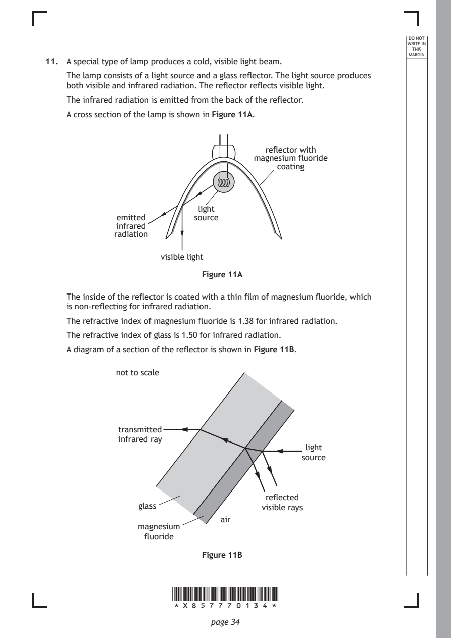
Selectable page text
DO NOT
                                                                  WRITE IN
                                                                   THIS
                                                                  MARGIN
11. A special type of lamp produces a cold, visible light beam.
    The lamp consists of a light source and a glass reflector. The light source produces
    both visible and infrared radiation. The reflector reflects visible light.
    The infrared radiation is emitted from the back of the reflector.
    A cross section of the lamp is shown in Figure 11A.

                                        reflector with
                                      magnesium fluoride
                                          coating

                            light
             emitted       source
             infrared
             radiation

                     visible light

                             Figure 11A

    The inside of the reflector is coated with a thin film of magnesium fluoride, which
    is non-reflecting for infrared radiation.
    The refractive index of magnesium fluoride is 1.38 for infrared radiation.

    The refractive index of glass is 1.50 for infrared radiation.
    A diagram of a section of the reflector is shown in Figure 11B.

             not to scale

              transmitted
              infrared ray
                                                light
                                               source

                                        reflected
                 glass                  visible rays
                                air
                 magnesium
                  fluoride

                             Figure 11B

                       *X857770134*

                              page 34
PDF page 35
Selectable page text
MARKS _{W}^{D}_{R}^{O}_{I} _{T}^{N}OT
                                                                    E IN
                                                                   THIS
                                                                  MARGIN
11. (continued)
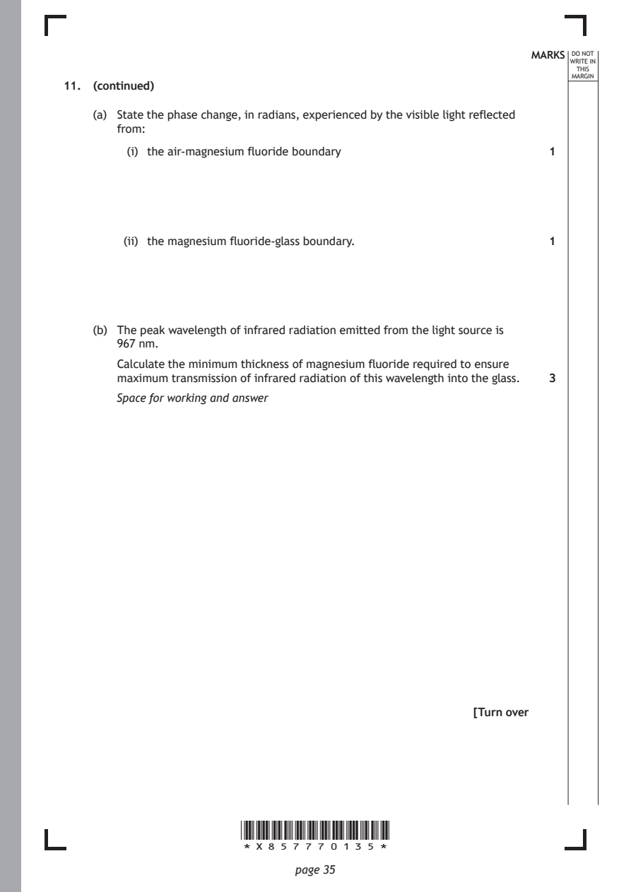
    (a) State the phase change, in radians, experienced by the visible light reflected
       from:
         (i) the air-magnesium fluoride boundary               1

        (ii) the magnesium fluoride-glass boundary.            1

    (b) The peak wavelength of infrared radiation emitted from the light source is
       967 nm.
       Calculate the minimum thickness of magnesium fluoride required to ensure
       maximum transmission of infrared radiation of this wavelength into the glass. 3

       Space for working and answer

                                                      [Turn over

                       *X857770135*

                              page 35
PDF page 36
Selectable page text
DO NOT
                                                                  WRITE IN
                                                                   THIS
                                                                  MARGIN
11. (continued)
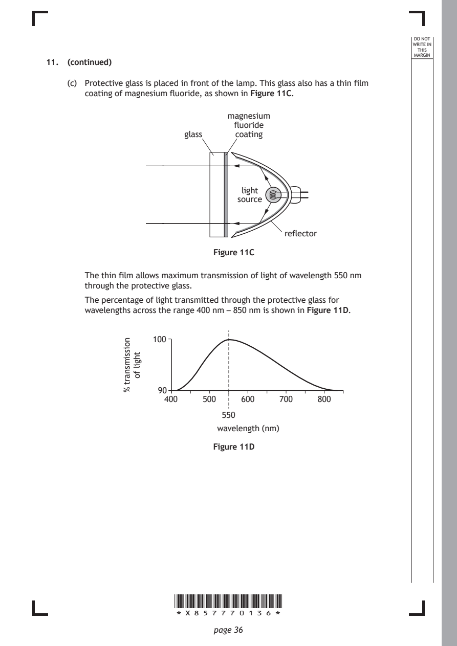
    (c) Protective glass is placed in front of the lamp. This glass also has a thin film
       coating of magnesium fluoride, as shown in Figure 11C.
                                 magnesium
                                  fluoride
                         glass    coating

                                   light
                                   source

                                           reflector

                              Figure 11C

       The thin film allows maximum transmission of light of wavelength 550 nm
       through the protective glass.

       The percentage of light transmitted through the protective glass for
       wavelengths across the range 400 nm – 850 nm is shown in Figure 11D.

                       *X857770136*

                              page 36
              noissimsnart
              %
                thgil
                fo
                   100
                    90
                      400   500    600    700    800
                                550
                               wavelength (nm)
                              Figure 11D
PDF page 37
Selectable page text
MARKS _{W}^{D}_{R}^{O}_{I} _{T}^{N}OT
                                                                    E IN
                                                                   THIS
                                                                  MARGIN
11. (c) (continued)
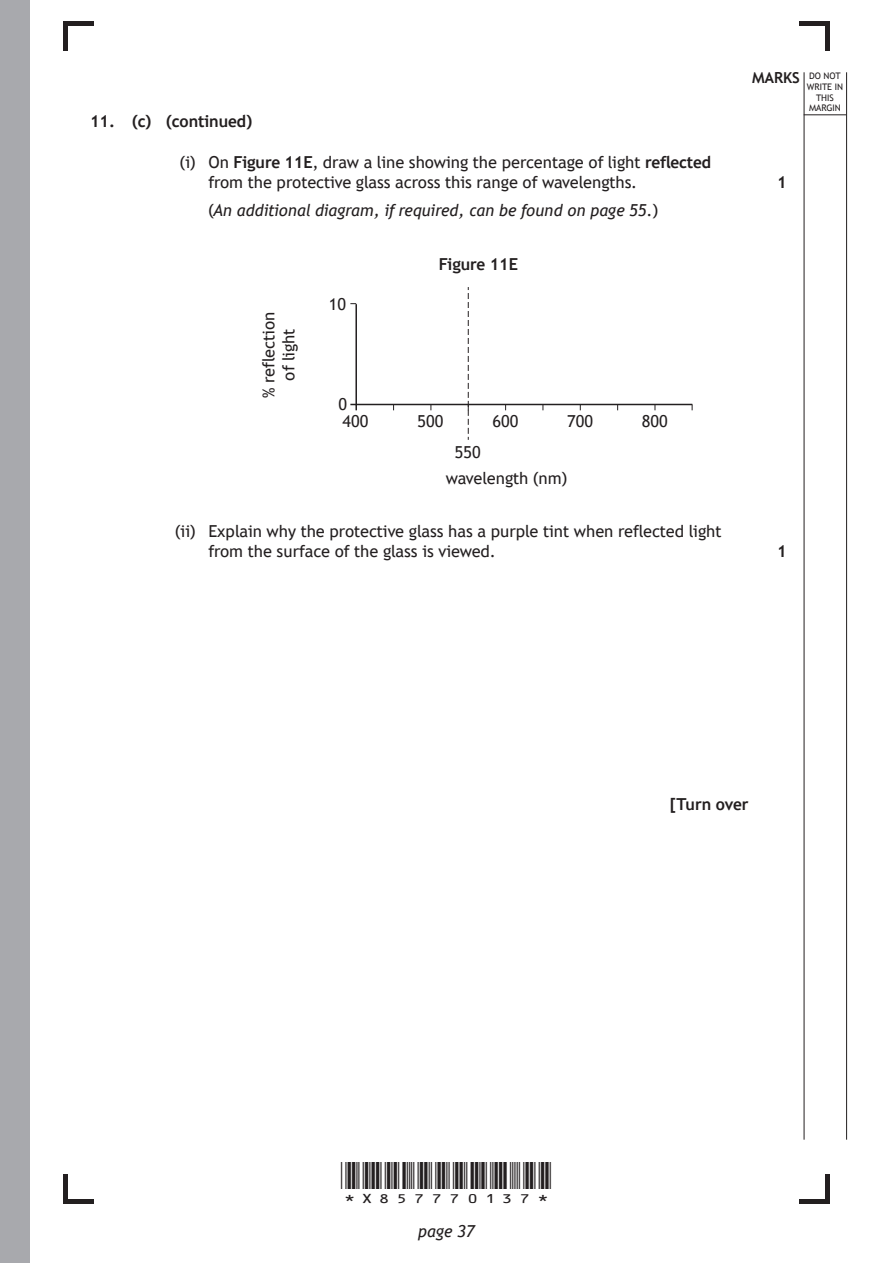
         (i) On Figure 11E, draw a line showing the percentage of light reflected
           from the protective glass across this range of wavelengths.
           (An additional diagram, if required, can be found on page 55.)

                                Figure 11E

                       *X857770137*

                              page 37
                noitcelfer
                %
                  thgil
                  fo
                                                               1
                      10
                       0
                       400    500    600    700    800
                                  550
                                 wavelength (nm)
        (ii) Explain why the protective glass has a purple tint when reflected light
           from the surface of the glass is viewed.            1
                                                      [Turn over
PDF page 38
Question 12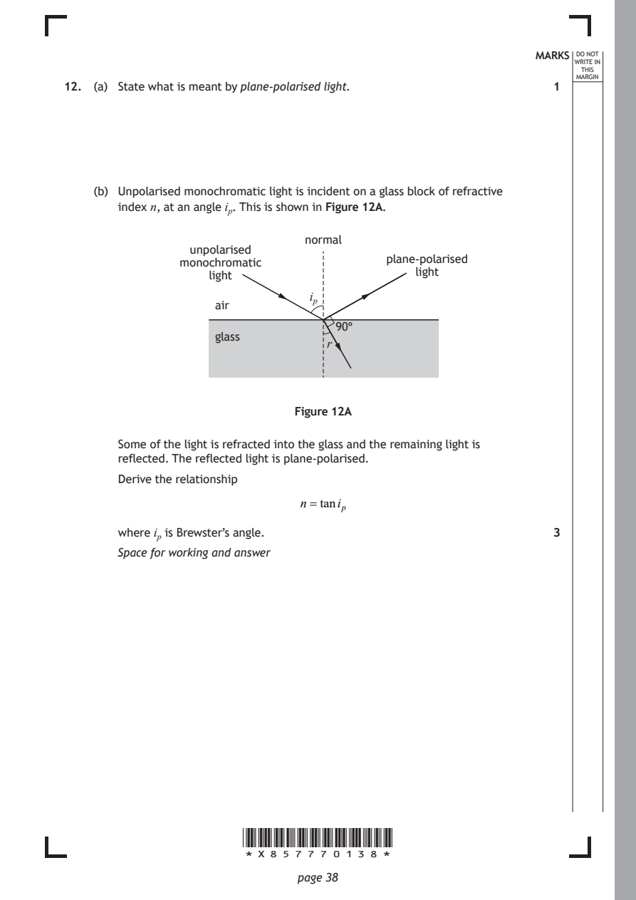
Selectable page text
MARKS _{W}^{D}_{R}^{O}_{I} _{T}^{N}OT
                                                                    E IN
                                                                   THIS
                                                                   ARGIN
12. (a) State what is meant by plane-polarised light.          1  ^{M}

    (b) Unpolarised monochromatic light is incident on a glass block of refractive

       index n, at an angle iₚ. This is shown in Figure 12A.

                               normal
                 unpolarised
               monochromatic              plane-polarised
                   light                      light
                                iₚ
                    air
                                   90°
                    glass
                                  r

                              Figure 12A

       Some of the light is refracted into the glass and the remaining light is
       reflected. The reflected light is plane-polarised.
       Derive the relationship

                               n=taniₚ

       where iₚ is Brewster’s angle.                           3
       Space for working and answer

                       *X857770138*

                              page 38
PDF page 39
Selectable page text
12. (continued)                                              MARKS _{W}^{D}_{R}^{O}_{I} _{T}^{N}OT
                                                                    E IN
                                                                   THIS
                                                                  MARGIN
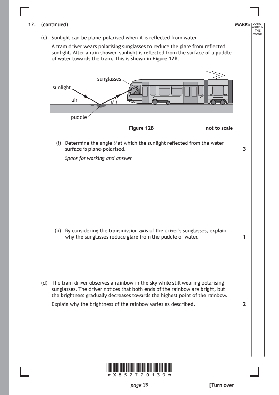
    (c) Sunlight can be plane-polarised when it is reflected from water.
       A tram driver wears polarising sunglasses to reduce the glare from reflected
       sunlight. After a rain shower, sunlight is reflected from the surface of a puddle
       of water towards the tram. This is shown in Figure 12B.

                     sunglasses
        sunlight

             air
                         θ

             puddle

                              Figure 12B             not to scale

         (i) Determine the angle θ at which the sunlight reflected from the water
           surface is plane-polarised.                         3

           Space for working and answer

        (ii) By considering the transmission axis of the driver’s sunglasses, explain
           why the sunglasses reduce glare from the puddle of water. 1

    (d) The tram driver observes a rainbow in the sky while still wearing polarising
       sunglasses. The driver notices that both ends of the rainbow are bright, but
       the brightness gradually decreases towards the highest point of the rainbow.

       Explain why the brightness of the rainbow varies as described. 2

                       *X857770139*

                              page 39                 [Turn over
PDF page 40
Question 13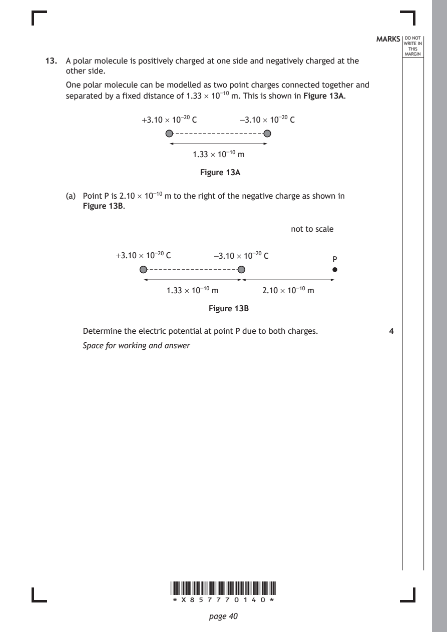
Selectable page text
MARKS _{W}^{D}_{R}^{O}_{I} _{T}^{N}OT
                                                                    E IN
                                                                   THIS
                                                                  MARGIN
13. A polar molecule is positively charged at one side and negatively charged at the
    other side.
    One polar molecule can be modelled as two point charges connected together and
    separated by a fixed distance of 1.33 × 10⁻¹⁰ m. This is shown in Figure 13A.
                  +3.10 × 10⁻²⁰ C   −3.10 × 10⁻²⁰ C

                           1.33 × 10⁻¹⁰ m

                             Figure 13A

    (a) Point P is 2.10 × 10⁻¹⁰ m to the right of the negative charge as shown in
       Figure 13B.

                                             not to scale

             +3.10 × 10⁻²⁰ C   −3.10 × 10⁻²⁰ C
                                                     P

                       1.33 × 10⁻¹⁰ m   2.10 × 10⁻¹⁰ m

                              Figure 13B

       Determine the electric potential at point P due to both charges. 4
       Space for working and answer

                       *X857770140*

                              page 40
PDF page 41
Selectable page text
MARKS _{W}^{D}_{R}^{O}_{I} _{T}^{N}OT
                                                                    E IN
                                                                   THIS
                                                                  MARGIN
13. (continued)
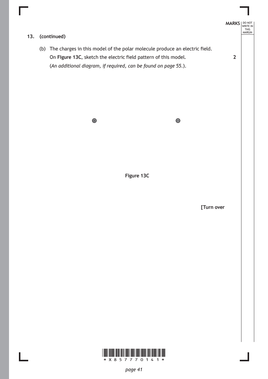
    (b) The charges in this model of the polar molecule produce an electric field.
       On Figure 13C, sketch the electric field pattern of this model. 2
       (An additional diagram, if required, can be found on page 55.).

                    +                         −

                              Figure 13C

                                                      [Turn over

                       *X857770141*

                              page 41
PDF page 42
Selectable page text
MARKS _{W}^{D}_{R}^{O}_{I} _{T}^{N}OT
                                                                    E IN
                                                                   THIS
                                                                  MARGIN
13. (continued)
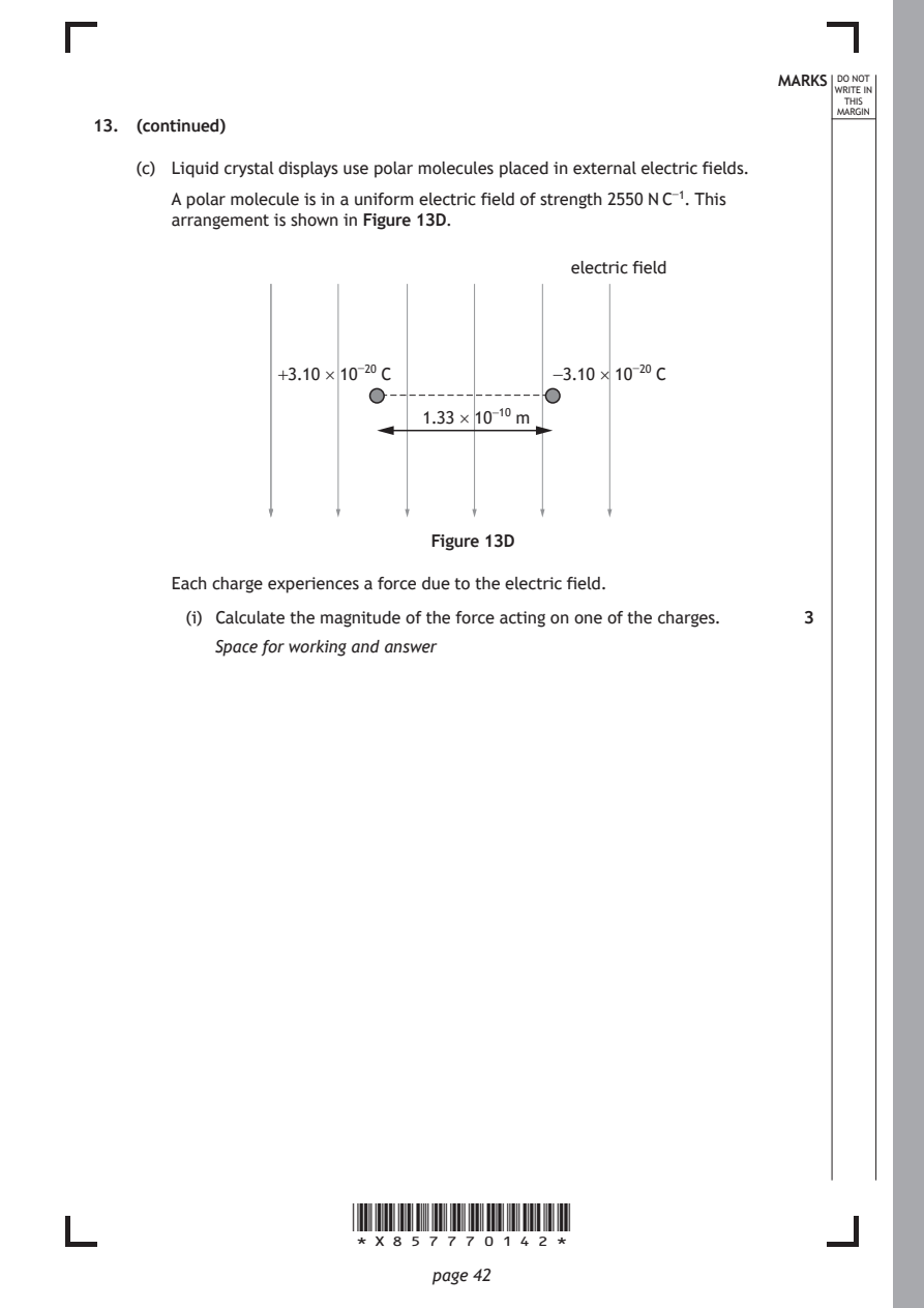
    (c) Liquid crystal displays use polar molecules placed in external electric fields.
       A polar molecule is in a uniform electric field of strength 2550 N C⁻¹. This
       arrangement is shown in Figure 13D.

                                           electric field

                 +3.10 × 10⁻²⁰ C         −3.10 × 10⁻²⁰ C

                              1.33 × 10⁻¹⁰ m

                              Figure 13D

       Each charge experiences a force due to the electric field.
         (i) Calculate the magnitude of the force acting on one of the charges. 3

           Space for working and answer

                       *X857770142*

                              page 42
PDF page 43
Selectable page text
MARKS _{W}^{D}_{R}^{O}_{I} _{T}^{N}OT
                                                                    E IN
                                                                   THIS
                                                                  MARGIN
13. (c) (continued)
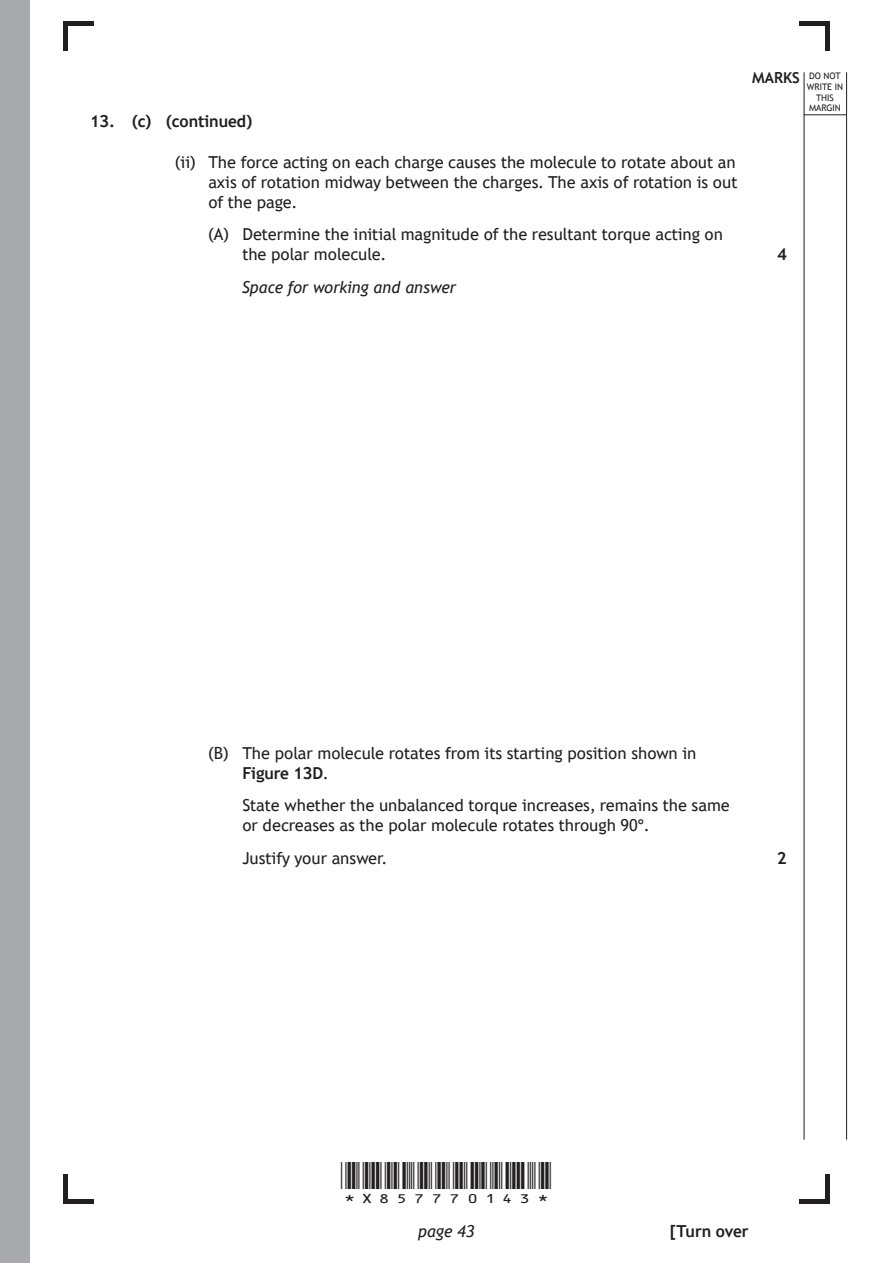
        (ii) The force acting on each charge causes the molecule to rotate about an
           axis of rotation midway between the charges. The axis of rotation is out
           of the page.
           (A) Determine the initial magnitude of the resultant torque acting on
              the polar molecule.                              4
              Space for working and answer

           (B) The polar molecule rotates from its starting position shown in
              Figure 13D.

              State whether the unbalanced torque increases, remains the same
              or decreases as the polar molecule rotates through 90°.

              Justify your answer.                             2

                       *X857770143*

                              page 43                 [Turn over
PDF page 44
Question 14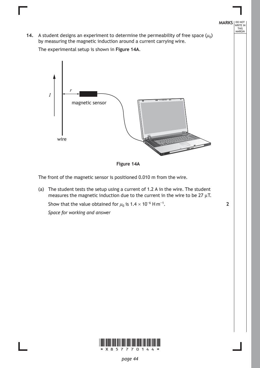
Selectable page text
MARKS _{W}^{D}_{R}^{O}_{I} _{T}^{N}OT
                                                                    E IN
                                                                   THIS
                                                                  MARGIN
14. A student designs an experiment to determine the permeability of free space (μ₀)
    by measuring the magnetic induction around a current carrying wire.
    The experimental setup is shown in Figure 14A.

              r
       I
               magnetic sensor

          wire

                             Figure 14A

    The front of the magnetic sensor is positioned 0.010 m from the wire.

    (a) The student tests the setup using a current of 1.2 A in the wire. The student
       measures the magnetic induction due to the current in the wire to be 27 µT.

       Show that the value obtained for μ₀ is 1.4 × 10⁻⁶ H m⁻¹. 2
       Space for working and answer

                       *X857770144*

                              page 44
PDF page 45
Selectable page text
MARKS _{W}^{D}_{R}^{O}_{I} _{T}^{N}OT
                                                                    E IN
                                                                   THIS
                                                                  MARGIN
14. (continued)
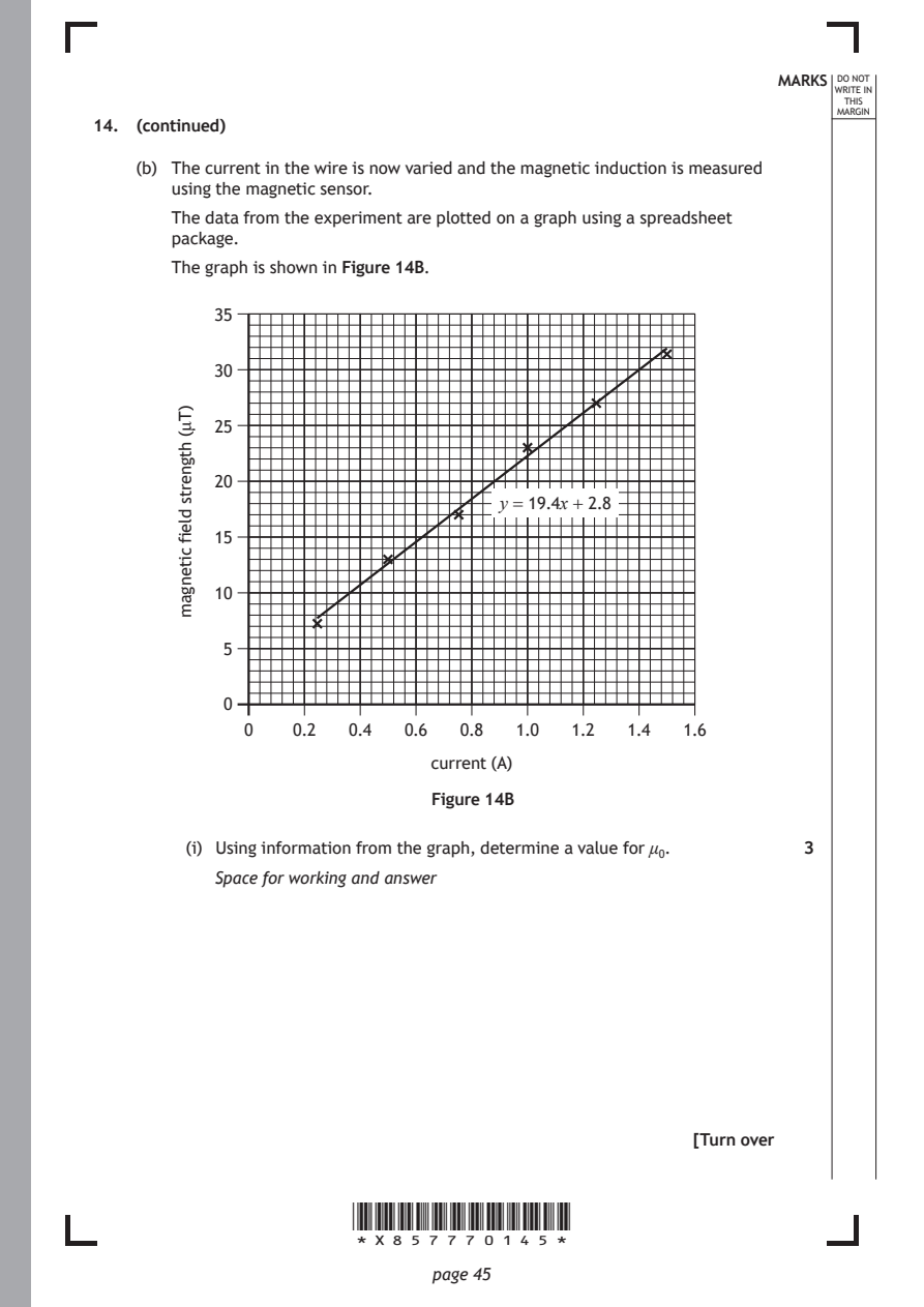
    (b) The current in the wire is now varied and the magnetic induction is measured
       using the magnetic sensor.
       The data from the experiment are plotted on a graph using a spreadsheet
       package.
       The graph is shown in Figure 14B.

           35

           30

           25

           20

           15

           10

            5

            0

                              current (A)

                       *X857770145*

                              page 45
        )Tμ(
        htgnerts
        dleif
        citengam
                                    y = 19.4x + 2.8
              0   0.2  0.4  0.6  0.8  1.0  1.2  1.4  1.6
                              Figure 14B
         (i) Using information from the graph, determine a value for μ₀. 3
           Space for working and answer
                                                      [Turn over
PDF page 46
Selectable page text
14. (b) (continued)                                          MARKS _{W}^{D}_{R}^{O}_{I} _{T}^{N}OT
                                                                    E IN
                                                                   THIS
                                                                  MARGIN
        (ii) Explain why the student should have more confidence in the value
           obtained for μ₀ in (b) (i).                         1

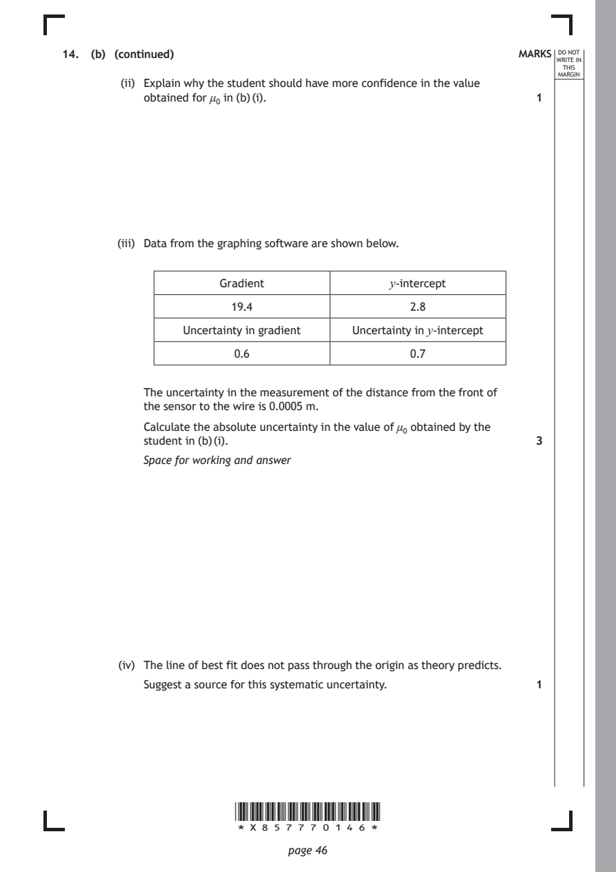
        (iii) Data from the graphing software are shown below.

                     Gradient               y-intercept
                       19.4                    2.8

                Uncertainty in gradient Uncertainty in y-intercept

                       0.6                     0.7

           The uncertainty in the measurement of the distance from the front of
           the sensor to the wire is 0.0005 m.
           Calculate the absolute uncertainty in the value of μ₀ obtained by the
           student in (b) (i).                                 3

           Space for working and answer

        (iv) The line of best fit does not pass through the origin as theory predicts.
           Suggest a source for this systematic uncertainty.   1

                       *X857770146*

                              page 46
PDF page 47
Question 15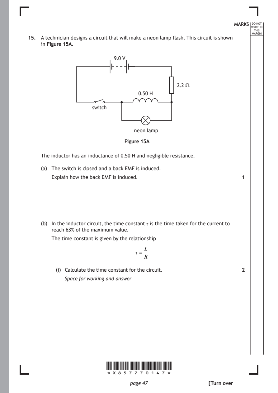
Selectable page text
MARKS _{W}^{D}_{R}^{O}_{I} _{T}^{N}OT
                                                                    E IN
                                                                   THIS
                                                                  MARGIN
15. A technician designs a circuit that will make a neon lamp flash. This circuit is shown
    in Figure 15A.
                          9.0 V

                                            2.2 Ω
                                 0.50 H

                   switch

                                neon lamp

                             Figure 15A

    The inductor has an inductance of 0.50 H and negligible resistance.

    (a) The switch is closed and a back EMF is induced.

       Explain how the back EMF is induced.                    1

    (b) In the inductor circuit, the time constant τ is the time taken for the current to

       reach 63% of the maximum value.
       The time constant is given by the relationship

                                   L
                                τ =
                                   R
         (i) Calculate the time constant for the circuit.      2

           Space for working and answer

                       *X857770147*

                              page 47                 [Turn over
PDF page 48
Selectable page text
MARKS _{W}^{D}_{R}^{O}_{I} _{T}^{N}OT
                                                                    E IN
                                                                   THIS
                                                                  MARGIN
15. (b) (continued)
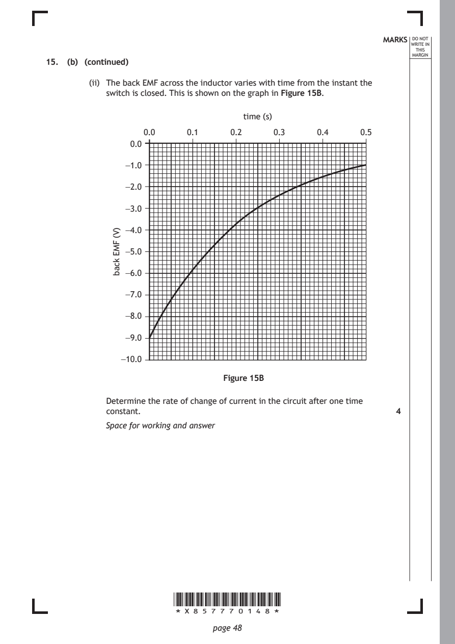
        (ii) The back EMF across the inductor varies with time from the instant the
           switch is closed. This is shown on the graph in Figure 15B.
                                    time (s)

                       *X857770148*

                              page 48
            )V(
            FME
            kcab
                  0.0     0.1     0.2    0.3     0.4     0.5
                0.0
               −1.0
               −2.0
               −3.0
               −4.0
               −5.0
               −6.0
               −7.0
               −8.0
               −9.0
              −10.0
                                Figure 15B
           Determine the rate of change of current in the circuit after one time
           constant.                                           4
           Space for working and answer
PDF page 49
Selectable page text
MARKS _{W}^{D}_{R}^{O}_{I} _{T}^{N}OT
                                                                    E IN
                                                                   THIS
                                                                  MARGIN
15. (continued)
    (c) The neon lamp requires a potential difference of 80 V to conduct.
       The switch is opened and the neon lamp flashes.
       By considering the magnetic field around the inductor, explain why the back
       EMF produced is large enough to allow the neon lamp to flash. 1

    (d) The switch is replaced by an automatic switch.

       This switch is closed. After five time constants the switch opens automatically.
       The neon lamp flashes immediately when the switch opens and then the
       switch closes again. This cycle repeats and the neon lamp flashes at regular
       intervals.

         (i) Determine the frequency at which the neon lamp flashes. 2
           Space for working and answer

        (ii) The technician increases the inductance of the inductor and keeps all
           other components the same.
           State whether the frequency of the flashes will increase, stay the same or
           decrease.

           You must justify your answer.                       2

                                                      [Turn over

                       *X857770149*

                              page 49
PDF page 50
Question 16
Selectable page text
MARKS _{W}^{D}_{R}^{O}_{I} _{T}^{N}OT
                                                                    E IN
                                                                   THIS
                                                                  MARGIN
16. It is suggested that, around the year 1900, Lord Kelvin stated there was nothing
    new left to be discovered in physics and all that remained was more and more
    precise measurement.
    Using your knowledge of physics, comment on this statement. 3

                       *X857770150*

                              page 50
PDF page 51

Selectable page text
MARKS _{W}^{D}_{R}^{O}_{I} _{T}^{N}OT
                                                                    E IN
                                                                   THIS
                                                                  MARGIN
16. (continued)

                        [END OF QUESTION PAPER]

                       *X857770151*

                              page 51
PDF page 52

Selectable page text
*X857770152*

       page 52
PDF page 53

Selectable page text
*X857770153*

       page 53
PDF page 54
Selectable page text
MARKS _{W}^{D}_{R}^{O}_{I} _{T}^{N}OT
                                                                    E IN
                                                                   THIS
                                                                  MARGIN
            ADDITIONAL SPACE FOR ANSWERS AND ROUGH WORK
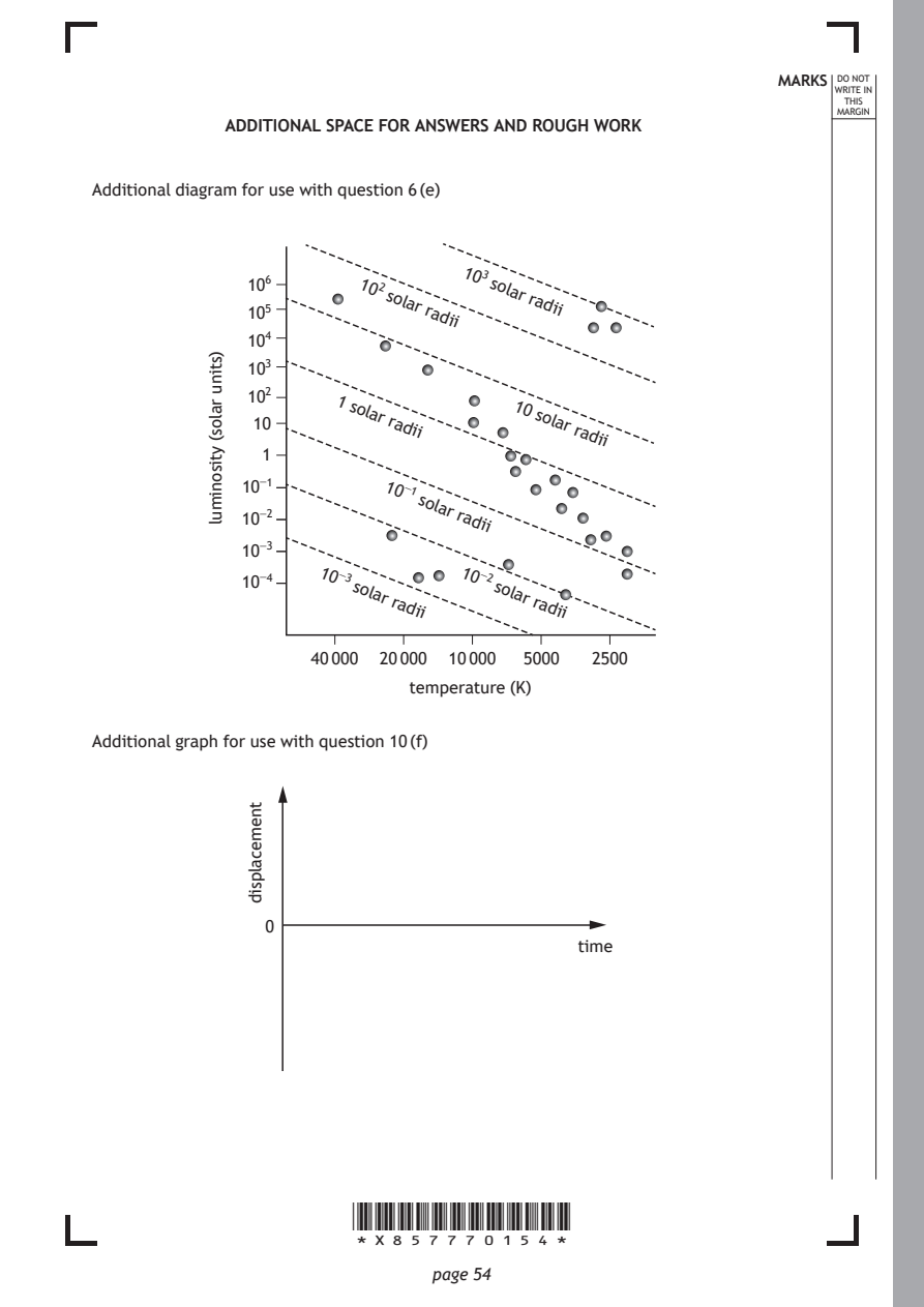
Additional diagram for use with question 6 (e)

                        102
                          solar
                              radii
                                 103
                                   solar
                                       radii
                      1
                       solar
                          radii
                                     10
                                       solar
                                           radii
                          10⁻¹
                             solar
                                radii
                    10⁻³         10⁻²
                       solar
                           radii
                                    solar
                                       radii
                    40 000 20 000 10 000 5000 2500
                            temperature (K)

                       *X857770154*

                              page 54
           )stinu
           ralos(
           ytisonimul
              10⁶
              10⁵
              10⁴
              10³
              10²
              10
               1
              10⁻¹
              10⁻²
              10⁻³
              10⁻⁴
Additional graph for use with question 10 (f)
                                           time
              tnemecalpsid
                0
PDF page 55
Selectable page text
MARKS _{W}^{D}_{R}^{O}_{I} _{T}^{N}OT
                                                                    E IN
                                                                   THIS
                                                                  MARGIN
            ADDITIONAL SPACE FOR ANSWERS AND ROUGH WORK
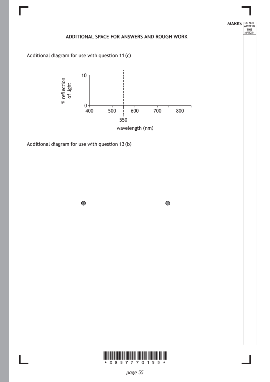
Additional diagram for use with question 11 (c)

                       *X857770155*

                              page 55
           noitcelfer
           %
            thgil
            fo
                 10
                  0
                  400    500    600    700    800
                            550
                            wavelength (nm)
Additional diagram for use with question 13 (b)
                 +                         −
PDF page 56

Selectable page text
MARKS _{W}^{D}_{R}^{O}_{I} _{T}^{N}OT
                                                        E IN
                                                       THIS
                                                      MARGIN
ADDITIONAL SPACE FOR ANSWERS AND ROUGH WORK

           *X857770156*

                  page 56
PDF page 57

Selectable page text
MARKS _{W}^{D}_{R}^{O}_{I} _{T}^{N}OT
                                                        E IN
                                                       THIS
                                                      MARGIN
ADDITIONAL SPACE FOR ANSWERS AND ROUGH WORK

           *X857770157*

                  page 57
PDF page 58

Selectable page text
[BLANK PAGE]

DO NOT WRITE ON THIS PAGE

*X857770158*

       page 58
PDF page 59

Selectable page text
[BLANK PAGE]

DO NOT WRITE ON THIS PAGE

*X857770159*

       page 59
PDF page 60

Selectable page text
[BLANK PAGE]

                       DO NOT WRITE ON THIS PAGE

Acknowledgement of copyright
Question 2 Vectorpocket/shutterstock.com
Question 4 Dima Zel/shutterstock.com

Question 5 Julia Kopacheva/shutterstock.com

                       *X857770160*

                              page 60