2022 Advanced Higher Physics questions
Source: Scottish Qualifications Authority (SQA) / Qualifications Scotland. This is a StemInteract HTML companion, not an official HTML edition. Selectable text is supplied alongside original page images. Use the images or original PDF for equations, powers, fractions, vector notation, tables and diagrams; text extraction cannot fully preserve mathematical layout.
Jump to a question
PDF page 1
Selectable page text
FOR OFFICIAL USE
AH
National
Qualications
Mark
2022
X857/77/01 Physics
FRIDAY, 13 MAY
9:00 AM – 12:00 NOON
*X8577701*
Fill in these boxes and read what is printed below.
Full name of centre Town
Forename(s) Surname Number of seat
Date of birth
Day Month Year Scottish candidate number
Total marks — 155
Attempt ALL questions.
Reference may be made to the Physics relationships sheet X857/77/11 and the data sheet on
page 02.
Write your answers clearly in the spaces provided in this booklet. Additional space for answers
and rough work is provided at the end of this booklet. If you use this space you must clearly
identify the question number you are attempting. Any rough work must be written in this
booklet. You should score through your rough work when you have written your final copy.
Care should be taken to give an appropriate number of significant figures in the final answers to
calculations.
Use blue or black ink.
Before leaving the examination room you must give this booklet to the Invigilator; if you do not,
you may lose all the marks for this paper.
©
*X857770101*
A/PBPDF page 2
Selectable page text
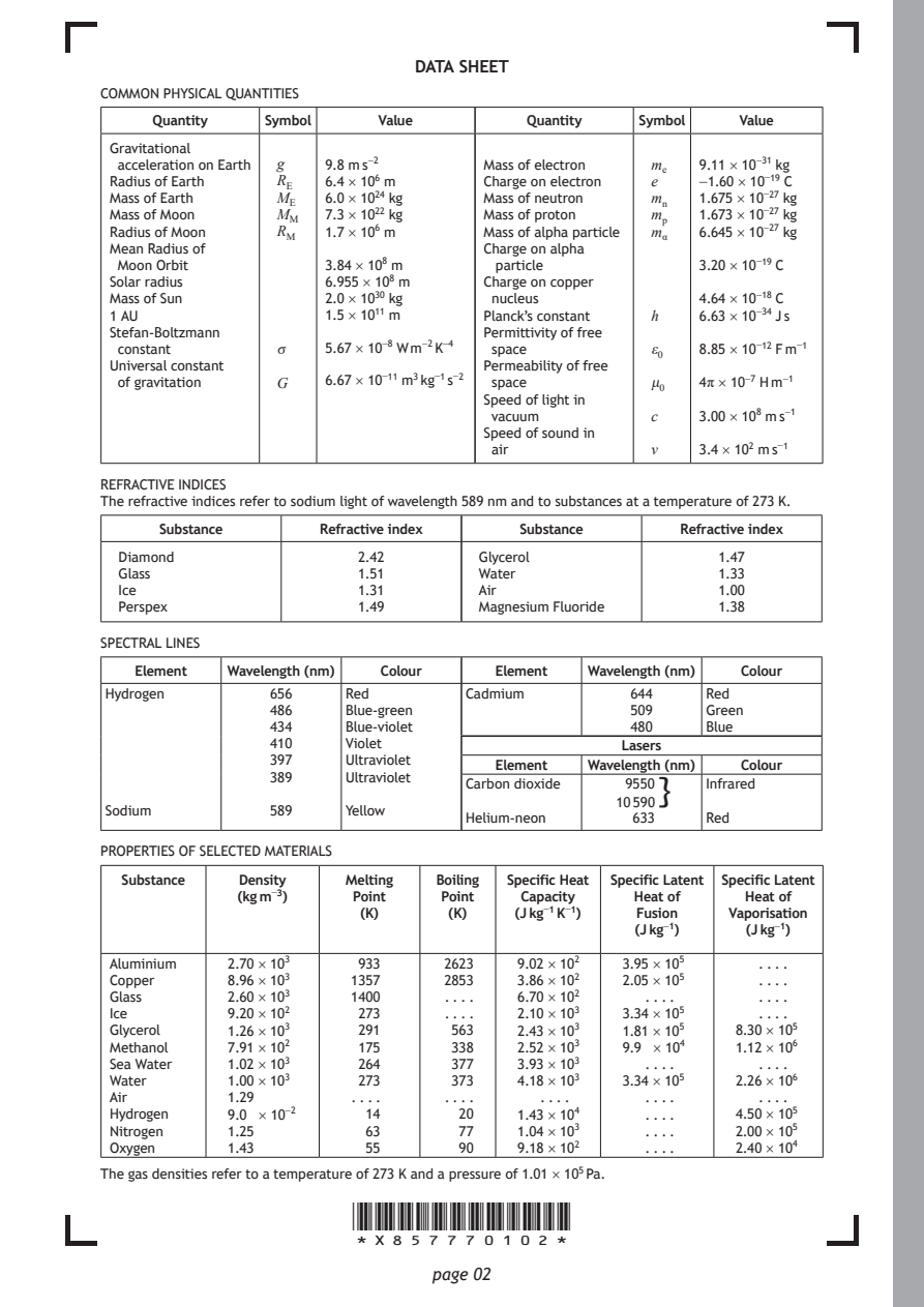
DATA SHEET
COMMON PHYSICAL QUANTITIES

     Quantity  Symbol    Value        Quantity  Symbol   Value
 Gravitational
 acceleration on Earth g 9.8 m s⁻² Mass of electron mₑ 9.11 × 10⁻³¹ kg
 Radius of Earth R_{E} 6.4 × 10⁶ m Charge on electron e −1.60 × 10⁻¹⁹ C
 Mass of Earth  M_{E} 6.0 × 10²⁴ kg Mass of neutron mₙ 1.675 × 10⁻²⁷ kg
 Mass of Moon   M_{M} 7.3 × 10²² kg Mass of proton mₚ 1.673 × 10⁻²⁷ kg
 Radius of Moon R_{M} 1.7 × 10⁶ m Mass of alpha particle m_{α} 6.645 × 10⁻²⁷ kg
 Mean Radius of                   Charge on alpha
 Moon Orbit         3.84 × 10⁸ m   particle          3.20 × 10⁻¹⁹ C
 Solar radius       6.955 × 10⁸ m Charge on copper
 Mass of Sun        2.0 × 10³⁰ kg  nucleus           4.64 × 10⁻¹⁸ C
 1 AU               1.5 × 10¹¹ m  Planck’s constant h 6.63 × 10⁻³⁴ J s
 Stefan-Boltzmann                 Permittivity of free
 constant       σ   5.67 × 10⁻⁸ W m⁻² K⁻⁴ space  ε₀  8.85 × 10⁻¹² F m⁻¹
 Universal constant               Permeability of free
 of gravitation G   6.67 × 10⁻¹¹ m³ kg⁻¹ s⁻² space μ₀ 4π × 10⁻⁷ H m⁻¹
                                  Speed of light in
                                   vacuum        c   3.00 × 10⁸ m s⁻¹
                                  Speed of sound in
                                   air           v   3.4 × 10² m s⁻¹
REFRACTIVE INDICES
The refractive indices refer to sodium light of wavelength 589 nm and to substances at a temperature of 273 K.
     Substance     Refractive index  Substance     Refractive index
  Diamond              2.42       Glycerol             1.47
  Glass                1.51       Water                1.33
  Ice                  1.31       Air                  1.00
  Perspex              1.49       Magnesium Fluoride   1.38
SPECTRAL LINES
   Element Wavelength (nm) Colour  Element Wavelength (nm) Colour
Hydrogen       656    Red       Cadmium        644    Red
               486    Blue-green               509    Green
               434    Blue-violet              480    Blue
               410    Violet                  Lasers
               397    Ultraviolet
                                   Element Wavelength (nm) Colour
               389    Ultraviolet
                                Carbon dioxide 9550}  Infrared
                                              10 590
Sodium         589    Yellow
                                Helium-neon    633    Red
PROPERTIES OF SELECTED MATERIALS
  Substance Density   Melting Boiling Specific Heat Specific Latent Specific Latent
            (kg m⁻³)  Point   Point  Capacity  Heat of   Heat of
                       (K)     (K)   (J kg⁻¹ K⁻¹) Fusion Vaporisation
                                               (J kg⁻¹)  (J kg⁻¹)
 Aluminium 2.70 × 10³  933    2623   9.02 × 10² 3.95 × 10⁵ . . . .
 Copper    8.96 × 10³ 1357    2853   3.86 × 10² 2.05 × 10⁵ . . . .
 Glass     2.60 × 10³ 1400     . . . . 6.70 × 10² . . . . . . . .
 Ice       9.20 × 10²  273     . . . . 2.10 × 10³ 3.34 × 10⁵ . . . .
 Glycerol  1.26 × 10³  291     563   2.43 × 10³ 1.81 × 10⁵ 8.30 × 10⁵
 Methanol  7.91 × 10²  175     338   2.52 × 10³ 9.9 × 10⁴ 1.12 × 10⁶
 Sea Water 1.02 × 10³  264     377   3.93 × 10³ . . . .   . . . .
 Water     1.00 × 10³  273     373   4.18 × 10³ 3.34 × 10⁵ 2.26 × 10⁶
 Air       1.29       . . . .  . . . . . . . .  . . . .   . . . .
 Hydrogen  9.0 × 10⁻²  14       20   1.43 × 10⁴ . . . . 4.50 × 10⁵
 Nitrogen  1.25        63       77   1.04 × 10³ . . . . 2.00 × 10⁵
 Oxygen    1.43        55       90   9.18 × 10² . . . . 2.40 × 10⁴
The gas densities refer to a temperature of 273 K and a pressure of 1.01 × 10⁵ Pa.
                      *X857770102*
                             page 02
PDF page 3

Selectable page text
[Turn over for next question

DO NOT WRITE ON THIS PAGE

*X857770103*

       page 03
PDF page 4
Question 1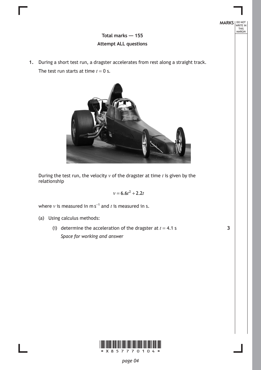
Selectable page text
MARKS _{W}^{D}_{R}^{O}_{I} _{T}^{N}OT
                                                                   E IN
                                                                  THIS
                                                                 MARGIN
                       Total marks — 155
                      Attempt ALL questions

1. During a short test run, a dragster accelerates from rest along a straight track.
   The test run starts at time t = 0 s.

   During the test run, the velocity v of the dragster at time t is given by the
   relationship

                           v=6.6t² +2.2t

   where v is measured in m s⁻¹ and t is measured in s.

   (a) Using calculus methods:

        (i) determine the acceleration of the dragster at t = 4.1 s 3
          Space for working and answer

                      *X857770104*

                             page 04
PDF page 5
Selectable page text
MARKS _{W}^{D}_{R}^{O}_{I} _{T}^{N}OT
                                                                   E IN
                                                                  THIS
                                                                 MARGIN
1. (a) (continued)
       (ii) determine the distance travelled by the dragster between t = 0 s and
          t = 4.1 s.                                          3
          Space for working and answer

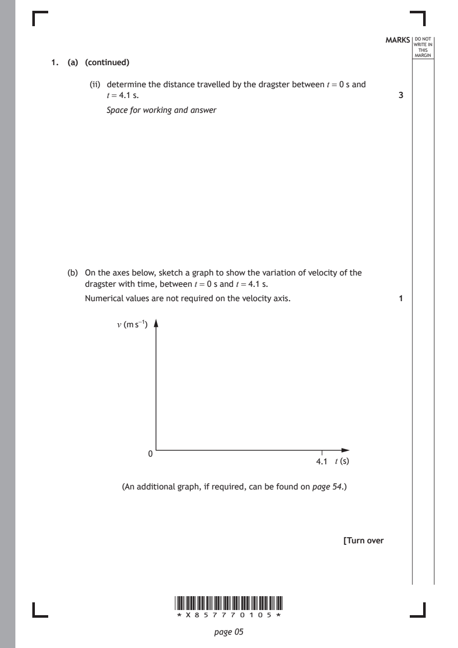
   (b) On the axes below, sketch a graph to show the variation of velocity of the
      dragster with time, between t = 0 s and t = 4.1 s.
      Numerical values are not required on the velocity axis. 1

            v (m s⁻¹)

                  0
                                                4.1 t (s)

             (An additional graph, if required, can be found on page 54.)

                                                     [Turn over

                      *X857770105*

                             page 05
PDF page 6
Question 2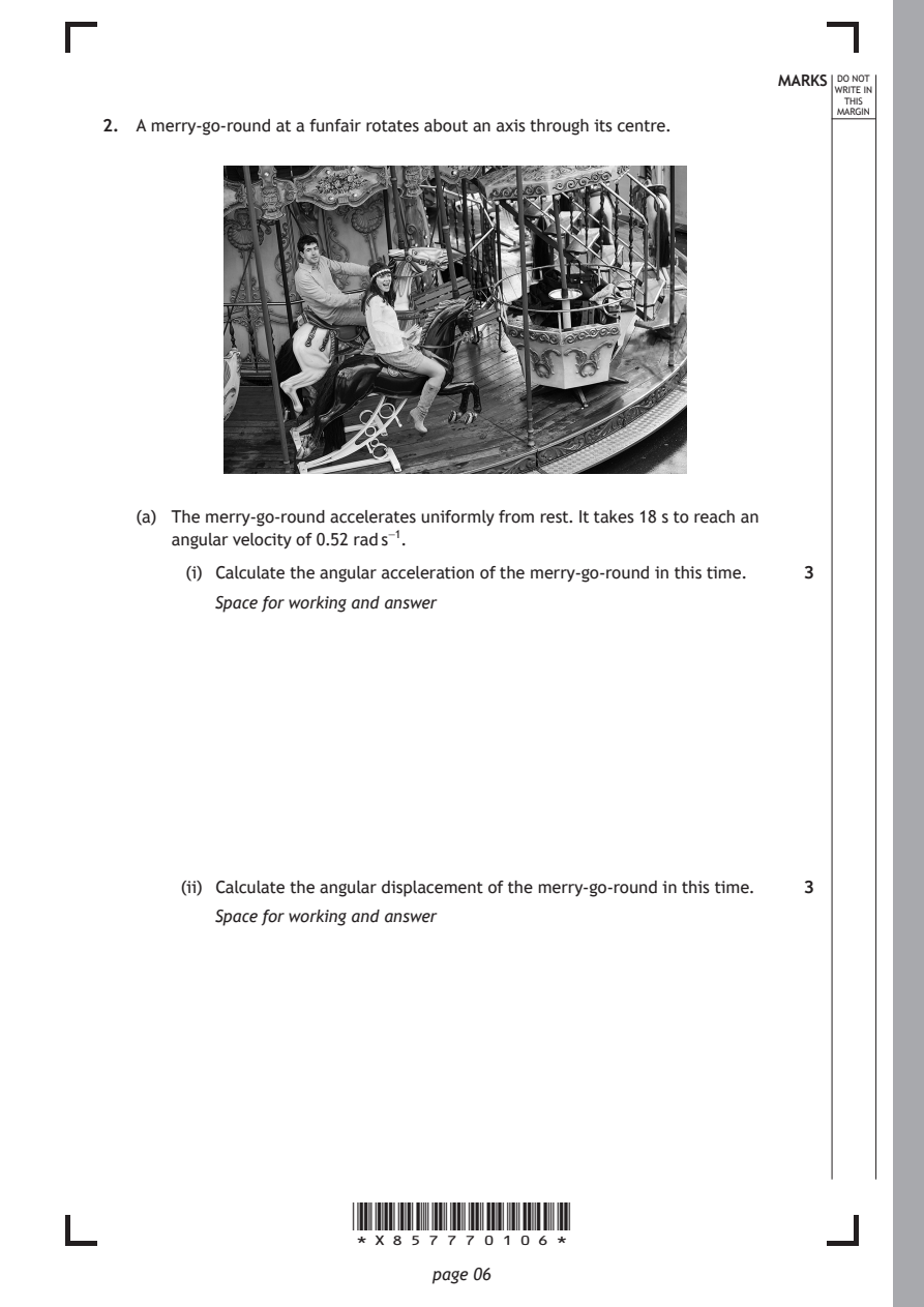
Selectable page text
MARKS _{W}^{D}_{R}^{O}_{I} _{T}^{N}OT
                                                                   E IN
                                                                  THIS
                                                                 MARGIN
2. A merry-go-round at a funfair rotates about an axis through its centre.

   (a) The merry-go-round accelerates uniformly from rest. It takes 18 s to reach an
      angular velocity of 0.52 rad s⁻¹.

        (i) Calculate the angular acceleration of the merry-go-round in this time. 3
          Space for working and answer

       (ii) Calculate the angular displacement of the merry-go-round in this time. 3
          Space for working and answer

                      *X857770106*

                             page 06
PDF page 7
Selectable page text
MARKS _{W}^{D}_{R}^{O}_{I} _{T}^{N}OT
                                                                   E IN
                                                                  THIS
                                                                 MARGIN
2. (continued)
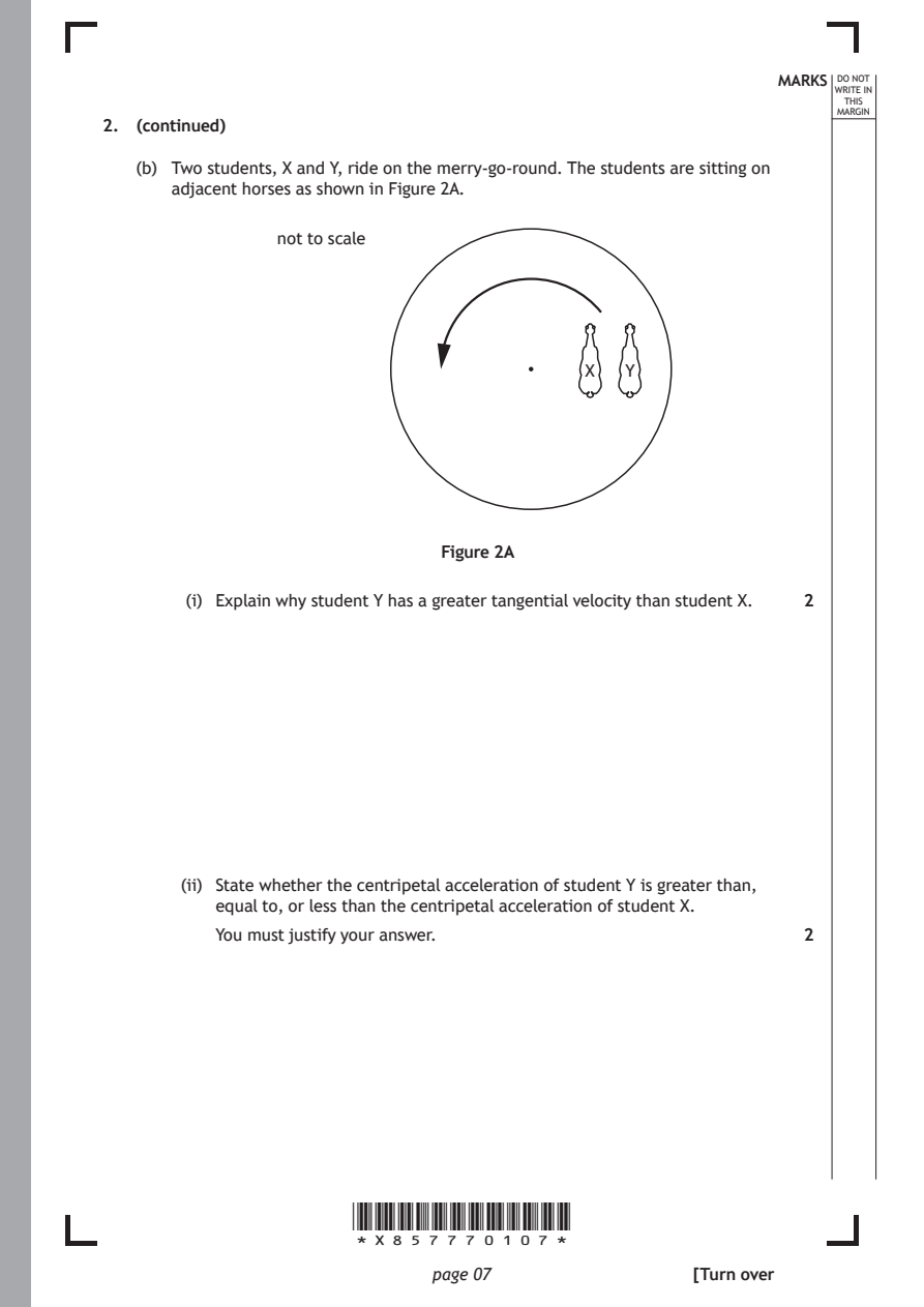
   (b) Two students, X and Y, ride on the merry-go-round. The students are sitting on
      adjacent horses as shown in Figure 2A.
                not to scale

                                           X   Y

                              Figure 2A

        (i) Explain why student Y has a greater tangential velocity than student X. 2

       (ii) State whether the centripetal acceleration of student Y is greater than,
          equal to, or less than the centripetal acceleration of student X.
          You must justify your answer.                       2

                      *X857770107*

                             page 07                 [Turn over
PDF page 8
Question 3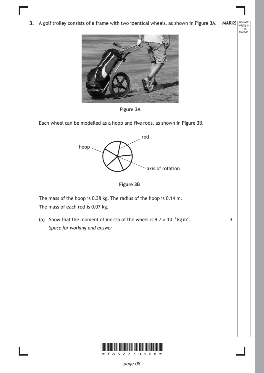
Selectable page text
3. A golf trolley consists of a frame with two identical wheels, as shown in Figure 3A. MARKS _{W}^{D}_{R}^{O}_{I} _{T}^{N}OT
                                                                   E IN
                                                                  THIS
                                                                 MARGIN

                            Figure 3A

   Each wheel can be modelled as a hoop and five rods, as shown in Figure 3B.

                                   rod

                hoop

                                     axis of rotation

                            Figure 3B

   The mass of the hoop is 0.38 kg. The radius of the hoop is 0.14 m.

   The mass of each rod is 0.07 kg.

   (a) Show that the moment of inertia of the wheel is 9.7 × 10⁻³ kg m². 3
      Space for working and answer

                      *X857770108*

                             page 08
PDF page 9
Selectable page text
3. (continued)                                              MARKS _{W}^{D}_{R}^{O}_{I} _{T}^{N}OT
                                                                   E IN
                                                                  THIS
                                                                 MARGIN
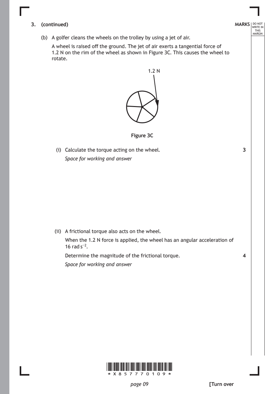
   (b) A golfer cleans the wheels on the trolley by using a jet of air.
      A wheel is raised off the ground. The jet of air exerts a tangential force of
      1.2 N on the rim of the wheel as shown in Figure 3C. This causes the wheel to
      rotate.
                                   1.2 N

                              Figure 3C

        (i) Calculate the torque acting on the wheel.         3

          Space for working and answer

       (ii) A frictional torque also acts on the wheel.
          When the 1.2 N force is applied, the wheel has an angular acceleration of
          16 rad s⁻².

          Determine the magnitude of the frictional torque.   4
          Space for working and answer

                      *X857770109*

                             page 09                 [Turn over
PDF page 10
Selectable page text
MARKS _{W}^{D}_{R}^{O}_{I} _{T}^{N}OT
                                                                   E IN
                                                                  THIS
                                                                 MARGIN
3. (continued)
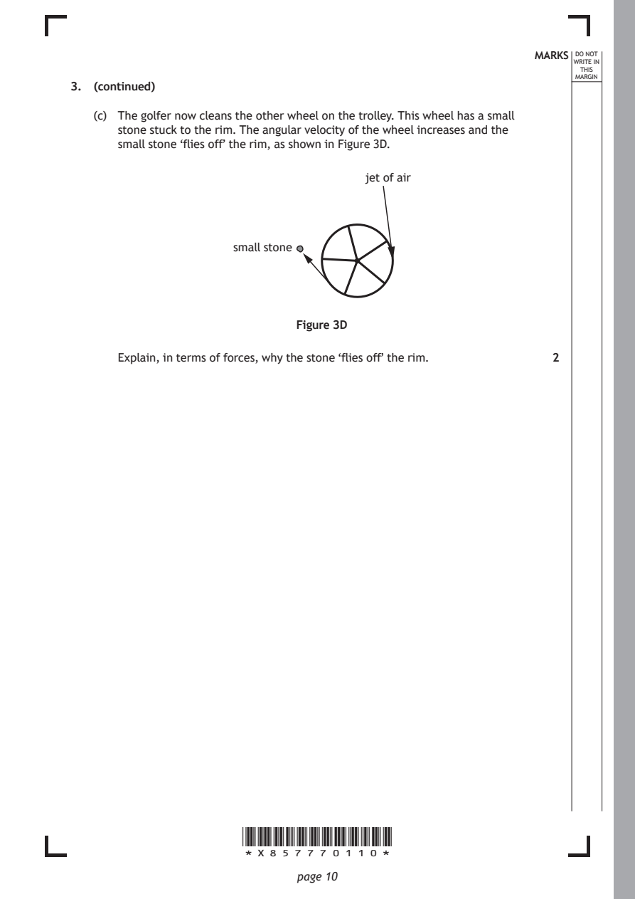
   (c) The golfer now cleans the other wheel on the trolley. This wheel has a small
      stone stuck to the rim. The angular velocity of the wheel increases and the
      small stone ‘flies off’ the rim, as shown in Figure 3D.
                                      jet of air

                     small stone

                             Figure 3D

      Explain, in terms of forces, why the stone ‘flies off’ the rim. 2

                      *X857770110*

                             page 10
PDF page 11

Selectable page text
[Turn over for next question

DO NOT WRITE ON THIS PAGE

*X857770111*

       page 11
PDF page 12
Question 4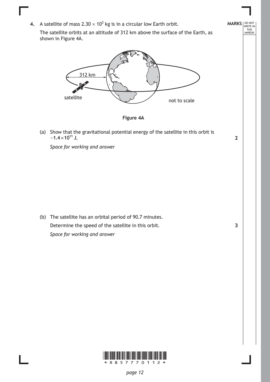
Selectable page text
4. A satellite of mass 2.30 × 10³ kg is in a circular low Earth orbit. MARKS _{W}^{D}_{R}^{O}_{I} _{T}^{N}OT
                                                                   E IN
                                                                  THIS
   The satellite orbits at an altitude of 312 km above the surface of the Earth, as MARGIN
   shown in Figure 4A.

               312 km

           satellite
                                          not to scale

                            Figure 4A

   (a) Show that the gravitational potential energy of the satellite in this orbit is
      −1.4×10¹¹ J.                                            2

      Space for working and answer

   (b) The satellite has an orbital period of 90.7 minutes.

      Determine the speed of the satellite in this orbit.     3
      Space for working and answer

                      *X857770112*

                             page 12
PDF page 13
Selectable page text
MARKS _{W}^{D}_{R}^{O}_{I} _{T}^{N}OT
                                                                   E IN
                                                                  THIS
                                                                 MARGIN
4. (continued)
   (c) Determine the total energy of the satellite in this orbit. 3
      Space for working and answer

   (d) Suggest why a satellite in a low-altitude orbit will lose energy at a greater rate
      than a similar satellite in a high-altitude orbit.      1

                                                     [Turn over

                      *X857770113*

                             page 13
PDF page 14
Selectable page text
MARKS _{W}^{D}_{R}^{O}_{I} _{T}^{N}OT
E IN
THIS
MARGIN
4. (continued)
(e) The gravitational fields of the Earth and the Moon create five Lagrangian
points.
A Lagrangian point is a position near two large bodies in orbit around each
other, where a smaller object, such as a satellite, will remain in a fixed
position relative to both orbiting bodies.
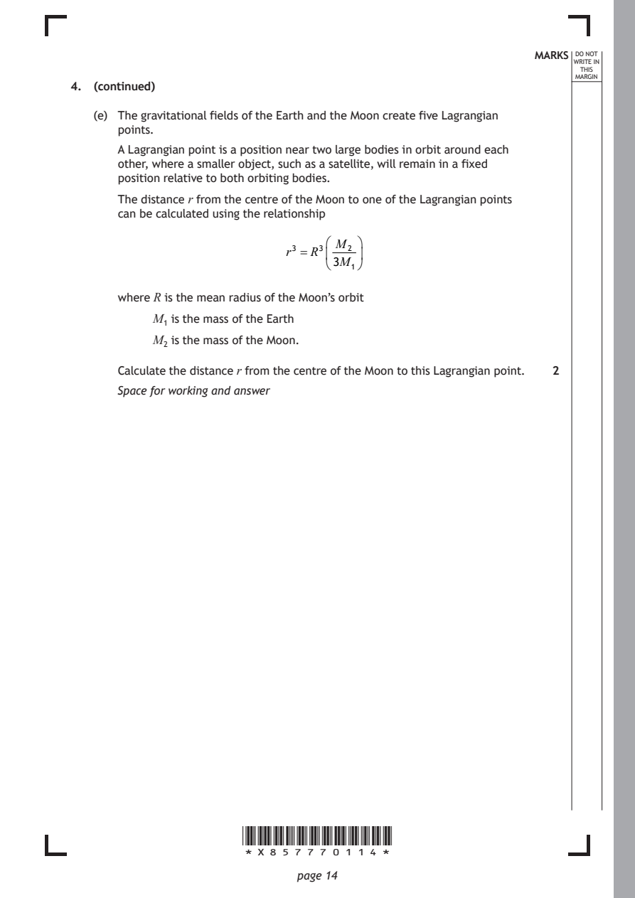
The distance r from the centre of the Moon to one of the Lagrangian points
can be calculated using the relationship
M₂
r³ = R³
3M₁
where R is the mean radius of the Moon’s orbit
M₁ is the mass of the Earth
M₂ is the mass of the Moon.
Calculate the distance r from the centre of the Moon to this Lagrangian point. 2
Space for working and answer
*X857770114*
page 14PDF page 15

Selectable page text
[Turn over for next question

DO NOT WRITE ON THIS PAGE

*X857770115*

       page 15
PDF page 16
Question 5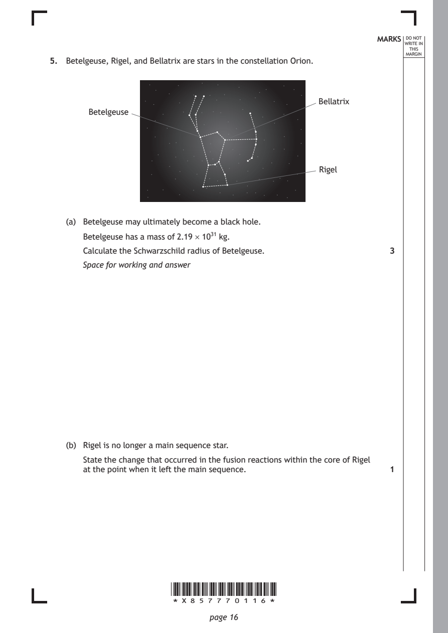
Selectable page text
MARKS _{W}^{D}_{R}^{O}_{I} _{T}^{N}OT
                                                                   E IN
                                                                  THIS
                                                                 MARGIN
5. Betelgeuse, Rigel, and Bellatrix are stars in the constellation Orion.

                                                 Bellatrix
       Betelgeuse

                                                 Rigel

   (a) Betelgeuse may ultimately become a black hole.

      Betelgeuse has a mass of 2.19 × 10³¹ kg.
      Calculate the Schwarzschild radius of Betelgeuse.       3

      Space for working and answer

   (b) Rigel is no longer a main sequence star.

      State the change that occurred in the fusion reactions within the core of Rigel
      at the point when it left the main sequence.            1

                      *X857770116*

                             page 16
PDF page 17
Selectable page text
MARKS _{W}^{D}_{R}^{O}_{I} _{T}^{N}OT
                                                                   E IN
                                                                  THIS
                                                                 MARGIN
5. (continued)
   (c) Bellatrix is approximately 250 ly from Earth. It has a radius of 4.0 × 10⁹ m and
      an apparent brightness of 5.0 × 10⁻⁸ W m⁻².
      Determine the surface temperature of Bellatrix.         5
      Space for working and answer

                                                     [Turn over

                      *X857770117*

                             page 17
PDF page 18
Selectable page text
MARKS _{W}^{D}_{R}^{O}_{I} _{T}^{N}OT
                                                                   E IN
                                                                  THIS
                                                                 MARGIN
5. (continued)
   (d) A group of students are discussing Rigel and Betelgeuse.
         Student 1: ‘ Why does Rigel appear to have a blue-white colour, while
                Betelgeuse appears orange in colour?’
         Student 2: ‘Betelgeuse also looks brighter than Rigel, so it must be closer.’

         Student 3: ‘ Betelgeuse and Rigel must be roughly the same distance from
                Earth, because they’re in the same constellation.’
         Student 4: ‘I don’t think Betelgeuse and Rigel are even in the same galaxy.’
      Use your knowledge of physics to comment on the discussion. 3

                      *X857770118*

                             page 18
PDF page 19

Selectable page text
DO NOT
                                                                 WRITE IN
                                                                  THIS
                                                                 MARGIN
5. (d) (continued)

                      *X857770119*

                             page 19                 [Turn over
PDF page 20
Question 6
Selectable page text
MARKS _{W}^{D}_{R}^{O}_{I} _{T}^{N}OT
                                                                   E IN
                                                                  THIS
                                                                 MARGIN
6. The Heisenberg uncertainty principle can be expressed as
                                  h
                           ΔxΔpₓ ≥
                                  4π
   (a) State an implication of this relationship for a quantum particle. 1

   (b) An alpha particle is emitted from a uranium-235 nucleus. According to classical
      physics, the alpha particle cannot overcome the strong nuclear force holding it
      in place in the nucleus.
      Explain, in terms of the Heisenberg uncertainty principle, why alpha emission

      is possible from the uranium-235 nucleus.               2

                      *X857770120*

                             page 20
PDF page 21
Selectable page text
MARKS _{W}^{D}_{R}^{O}_{I} _{T}^{N}OT
                                                                   E IN
                                                                  THIS
                                                                 MARGIN
6. (continued)
   (c) The mean lifetime of an alpha particle within the uranium-235 nucleus is
      0.70 µs.
      Determine the minimum uncertainty in the energy of this alpha particle. 3
      Space for working and answer

                                                     [Turn over

                      *X857770121*

                             page 21
PDF page 22
Question 7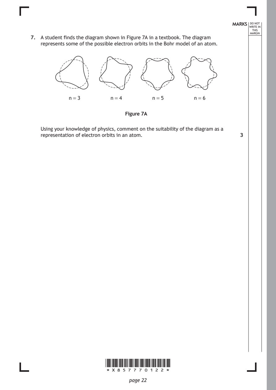
Selectable page text
MARKS _{W}^{D}_{R}^{O}_{I} _{T}^{N}OT
                                                                   E IN
                                                                  THIS
                                                                 MARGIN
7. A student finds the diagram shown in Figure 7A in a textbook. The diagram
   represents some of the possible electron orbits in the Bohr model of an atom.

           n = 3        n = 4       n = 5        n = 6

                            Figure 7A

   Using your knowledge of physics, comment on the suitability of the diagram as a
   representation of electron orbits in an atom.              3

                      *X857770122*

                             page 22
PDF page 23

Selectable page text
DO NOT
                                                                 WRITE IN
                                                                  THIS
                                                                 MARGIN
7. (continued)

                      *X857770123*

                             page 23                 [Turn over
PDF page 24
Question 8
Selectable page text
MARKS _{W}^{D}_{R}^{O}_{I} _{T}^{N}OT
                                                                   E IN
                                                                  THIS
                                                                 MARGIN
8. To produce an image of an atom, some microscopes use particles such as electrons
   or neutrons.
   The de Broglie wavelengths of the particles should be approximately the same
   magnitude as, or smaller than, the diameter of the atom being imaged.
   (a) In one electron microscope, the electrons used have a velocity of
      1.75 × 10⁷ m s⁻¹.
        (i) Calculate the de Broglie wavelength of the electrons used. 3

          Space for working and answer

       (ii) The diameter of an atom can be measured in ångströms (Å).

          1 Å is equal to 0.1 nm.
          The diameter of a gold atom is 2.6 Å.

          (A) Explain whether electrons with velocity 1.75 × 10⁷ m s⁻¹ are suitable
             for imaging the gold atom.                       1

                      *X857770124*

                             page 24
PDF page 25
Selectable page text
MARKS _{W}^{D}_{R}^{O}_{I} _{T}^{N}OT
                                                                   E IN
                                                                  THIS
                                                                 MARGIN
8. (a) (ii) (continued)
          (B) A neutron microscope uses neutrons with a velocity three orders of
             magnitude less than that of the electrons in the electron
             microscope.
             Explain fully why the neutron microscope is suitable for imaging
             gold atoms.                                      2

   (b) Optical microscopes use visible light. Individual atoms are too small to be
      viewed using an optical microscope.
      Estimate the diameter of the smallest object that could be imaged using an
      optical microscope.                                     1

                                                     [Turn over

                      *X857770125*

                             page 25
PDF page 26
Question 9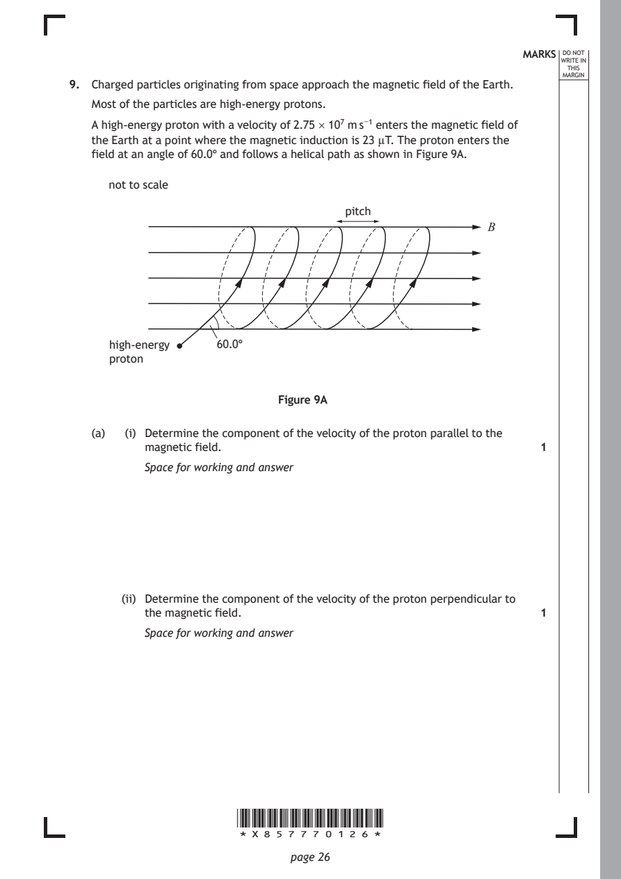
Selectable page text
MARKS _{W}^{D}_{R}^{O}_{I} _{T}^{N}OT
                                                                   E IN
                                                                  THIS
                                                                 MARGIN
9. Charged particles originating from space approach the magnetic field of the Earth.
   Most of the particles are high-energy protons.
   A high-energy proton with a velocity of 2.75 × 10⁷ m s⁻¹ enters the magnetic field of
   the Earth at a point where the magnetic induction is 23 µT. The proton enters the
   field at an angle of 60.0° and follows a helical path as shown in Figure 9A.
     not to scale

                                     pitch
                                                       B

     high-energy    60.0°
     proton

                            Figure 9A

   (a)  (i) Determine the component of the velocity of the proton parallel to the
          magnetic field.                                     1
          Space for working and answer

       (ii) Determine the component of the velocity of the proton perpendicular to
          the magnetic field.                                 1
          Space for working and answer

                      *X857770126*

                             page 26
PDF page 27
Selectable page text
9. (continued)                                              MARKS _{W}^{D}_{R}^{O}_{I} _{T}^{N}OT
                                                                   E IN
                                                                  THIS
                                                                 MARGIN
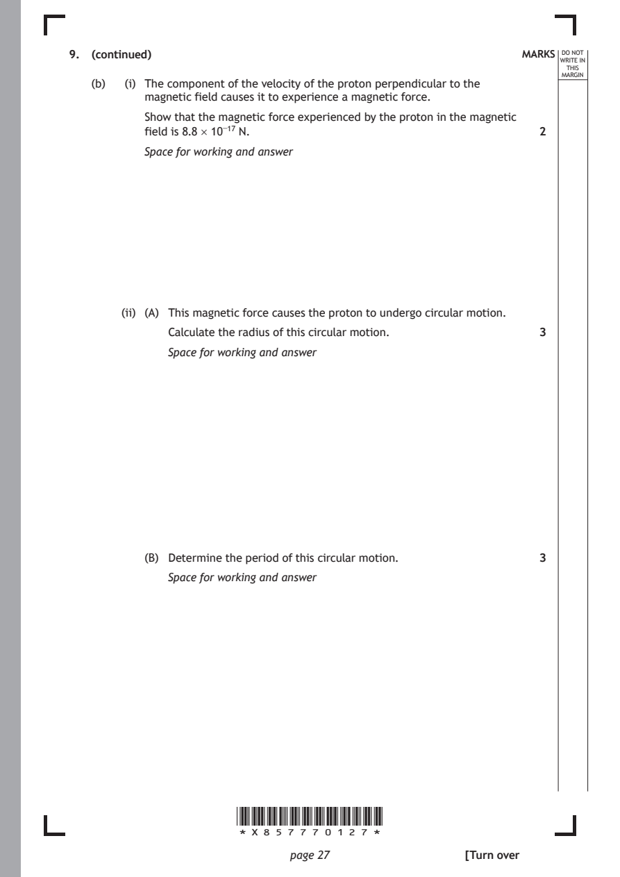
   (b)  (i) The component of the velocity of the proton perpendicular to the
          magnetic field causes it to experience a magnetic force.
          Show that the magnetic force experienced by the proton in the magnetic
          field is 8.8 × 10⁻¹⁷ N.                             2
          Space for working and answer

       (ii) (A) This magnetic force causes the proton to undergo circular motion.
             Calculate the radius of this circular motion.    3

             Space for working and answer

          (B) Determine the period of this circular motion.   3
             Space for working and answer

                      *X857770127*

                             page 27                 [Turn over
PDF page 28
Selectable page text
9. (b) (continued)                                          MARKS _{W}^{D}_{R}^{O}_{I} _{T}^{N}OT
                                                                   E IN
                                                                  THIS
                                                                 MARGIN
       (iii) The distance that the proton moves parallel to the magnetic field lines
          during one period of the circular motion is known as the pitch.
          Calculate the pitch of the helical path.            3
          Space for working and answer

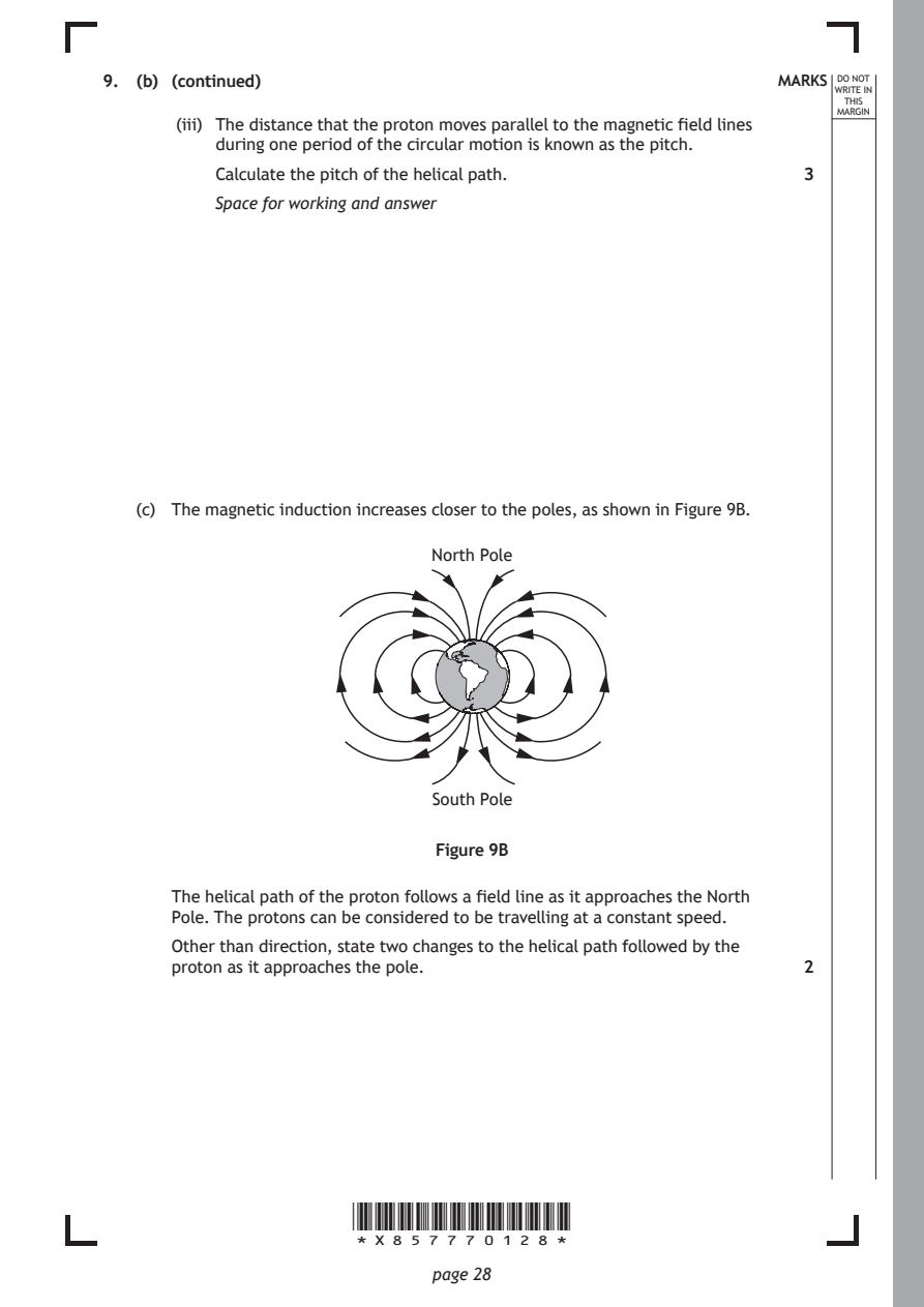
   (c) The magnetic induction increases closer to the poles, as shown in Figure 9B.

                             North Pole

                             South Pole

                              Figure 9B

      The helical path of the proton follows a field line as it approaches the North
      Pole. The protons can be considered to be travelling at a constant speed.

      Other than direction, state two changes to the helical path followed by the
      proton as it approaches the pole.                       2

                      *X857770128*

                             page 28
PDF page 29

Selectable page text
[Turn over for next question

DO NOT WRITE ON THIS PAGE

*X857770129*

       page 29
PDF page 30
Question 10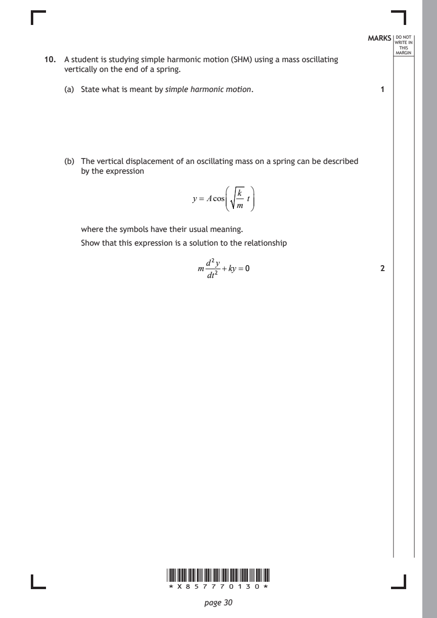
Selectable page text
MARKS _{W}^{D}_{R}^{O}_{I} _{T}^{N}OT
E IN
THIS
MARGIN
10. A student is studying simple harmonic motion (SHM) using a mass oscillating
vertically on the end of a spring.
(a) State what is meant by simple harmonic motion. 1
(b) The vertical displacement of an oscillating mass on a spring can be described
by the expression
k
y = Acos t
m
where the symbols have their usual meaning.
Show that this expression is a solution to the relationship
d²y
m +ky =0 2
dt²
*X857770130*
page 30PDF page 31
Selectable page text
MARKS _{W}^{D}_{R}^{O}_{I} _{T}^{N}OT
E IN
THIS
MARGIN
10. (continued)
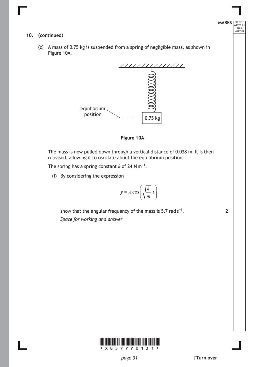
(c) A mass of 0.75 kg is suspended from a spring of negligible mass, as shown in
Figure 10A.
equilibrium
position
0.75 kg
Figure 10A
The mass is now pulled down through a vertical distance of 0.038 m. It is then
released, allowing it to oscillate about the equilibrium position.
The spring has a spring constant k of 24 N m⁻¹.
(i) By considering the expression
k
y = Acos t
m
show that the angular frequency of the mass is 5.7 rad s⁻¹. 2
Space for working and answer
*X857770131*
page 31 [Turn overPDF page 32
Selectable page text
MARKS _{W}^{D}_{R}^{O}_{I} _{T}^{N}OT
                                                                    E IN
                                                                   THIS
                                                                  MARGIN
10. (c) (continued)
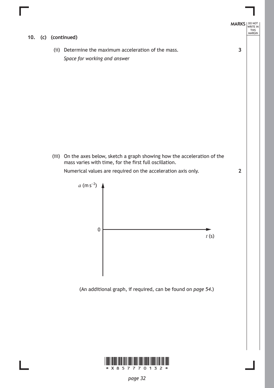
        (ii) Determine the maximum acceleration of the mass.   3
           Space for working and answer

        (iii) On the axes below, sketch a graph showing how the acceleration of the
           mass varies with time, for the first full oscillation.
           Numerical values are required on the acceleration axis only. 2

                a (m s⁻²)

                     0
                                                      t (s)

                (An additional graph, if required, can be found on page 54.)

                       *X857770132*

                              page 32
PDF page 33

Selectable page text
[Turn over for next question

DO NOT WRITE ON THIS PAGE

*X857770133*

       page 33
PDF page 34
Question 11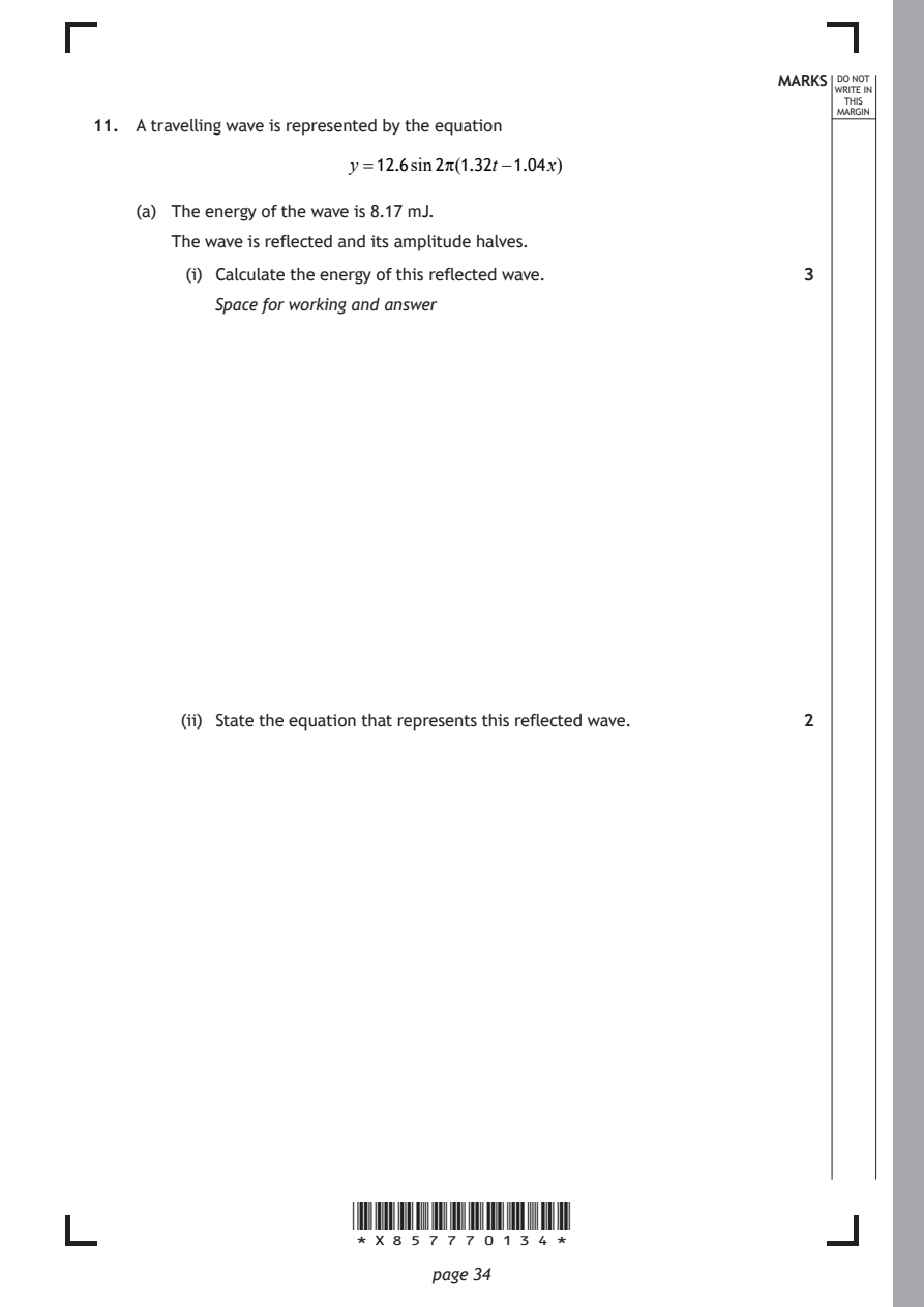
Selectable page text
MARKS _{W}^{D}_{R}^{O}_{I} _{T}^{N}OT
                                                                    E IN
                                                                   THIS
                                                                  MARGIN
11. A travelling wave is represented by the equation
                       y =12.6sin2π(1.32t−1.04x)
    (a) The energy of the wave is 8.17 mJ.

       The wave is reflected and its amplitude halves.
         (i) Calculate the energy of this reflected wave.      3

           Space for working and answer

        (ii) State the equation that represents this reflected wave. 2

                       *X857770134*

                              page 34
PDF page 35
Selectable page text
MARKS _{W}^{D}_{R}^{O}_{I} _{T}^{N}OT
                                                                    E IN
                                                                   THIS
                                                                  MARGIN
11. (continued)
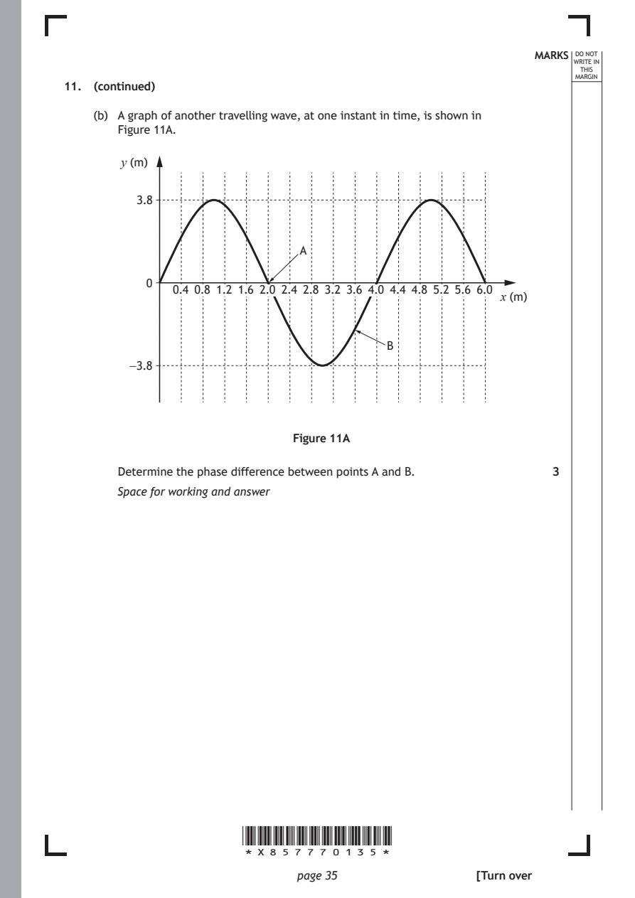
    (b) A graph of another travelling wave, at one instant in time, is shown in
       Figure 11A.
        y (m)

          3.8

                               A

           0
              0.4 0.8 1.2 1.6 2.0 2.4 2.8 3.2 3.6 4.0 4.4 4.8 5.2 5.6 6.0
                                                         x (m)

                                          B
         −3.8

                              Figure 11A

       Determine the phase difference between points A and B.  3
       Space for working and answer

                       *X857770135*

                              page 35                 [Turn over
PDF page 36
Question 12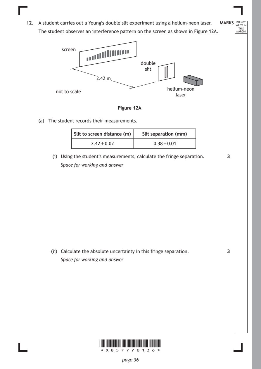
Selectable page text
12. A student carries out a Young’s double slit experiment using a helium-neon laser. MARKS _{W}^{D}_{R}^{O}_{I} _{T}^{N}OT
                                                                    E IN
                                                                   THIS
    The student observes an interference pattern on the screen as shown in Figure 12A. MARGIN
           screen

                                    double
                                      slit
                      2.42 m

                                             helium-neon
          not to scale
                                               laser

                             Figure 12A

    (a) The student records their measurements.

               Slit to screen distance (m) Slit separation (mm)

                     2.42±0.02          0.38±0.01

         (i) Using the student’s measurements, calculate the fringe separation. 3

           Space for working and answer

        (ii) Calculate the absolute uncertainty in this fringe separation. 3
           Space for working and answer

                       *X857770136*

                              page 36
PDF page 37
Selectable page text
MARKS _{W}^{D}_{R}^{O}_{I} _{T}^{N}OT
                                                                    E IN
                                                                   THIS
                                                                  MARGIN
12. (continued)
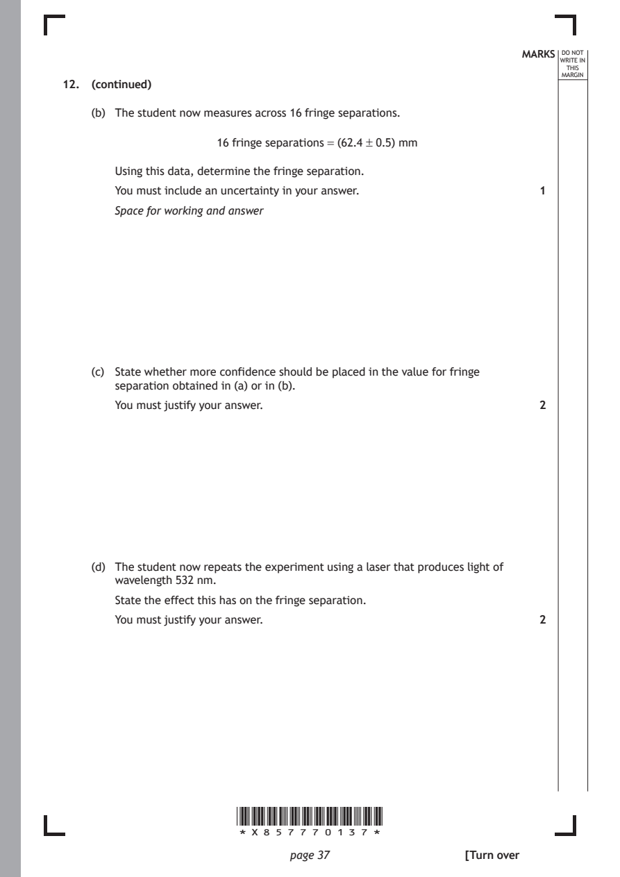
    (b) The student now measures across 16 fringe separations.
                     16 fringe separations = (62.4 ± 0.5) mm

       Using this data, determine the fringe separation.

       You must include an uncertainty in your answer.         1
       Space for working and answer

    (c) State whether more confidence should be placed in the value for fringe
       separation obtained in (a) or in (b).

       You must justify your answer.                           2

    (d) The student now repeats the experiment using a laser that produces light of

       wavelength 532 nm.
       State the effect this has on the fringe separation.
       You must justify your answer.                           2

                       *X857770137*

                              page 37                 [Turn over
PDF page 38
Question 13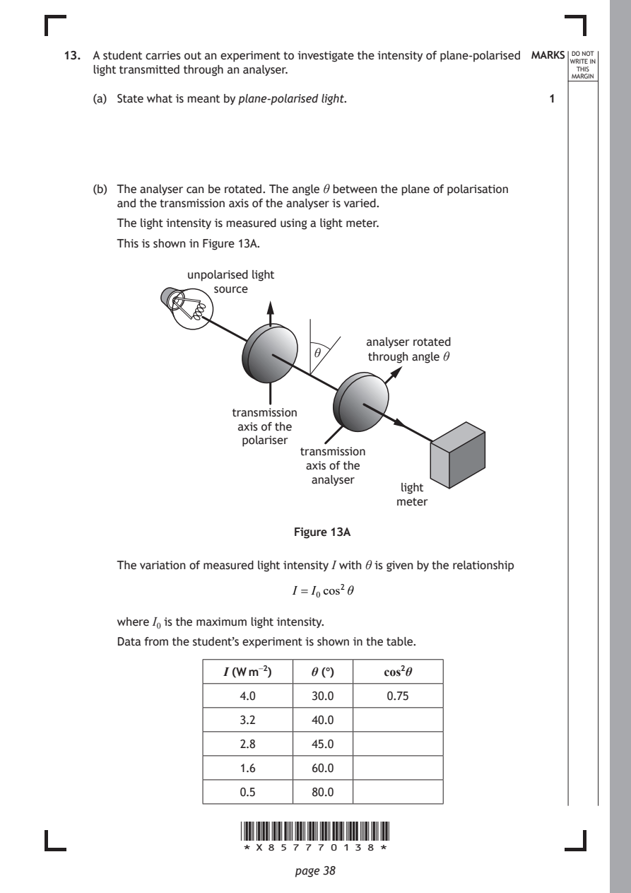
Selectable page text
13. A student carries out an experiment to investigate the intensity of plane-polarised MARKS _{W}^{D}_{R}^{O}_{I} _{T}^{N}OT
                                                                    E IN
    light transmitted through an analyser.                         THIS
                                                                  MARGIN
    (a) State what is meant by plane‑polarised light.          1

    (b) The analyser can be rotated. The angle θ between the plane of polarisation
       and the transmission axis of the analyser is varied.

       The light intensity is measured using a light meter.
       This is shown in Figure 13A.

                unpolarised light
                    source

                                        analyser rotated
                                 θ
                                        through angle θ

                      transmission
                       axis of the
                       polariser
                               transmission
                                axis of the
                                 analyser
                                            light
                                            meter
                              Figure 13A

       The variation of measured light intensity I with θ is given by the relationship
                              I = I₀cos²θ

       where I₀ is the maximum light intensity.
       Data from the student’s experiment is shown in the table.

                     I (W m⁻²)   θ (°)    cos²θ

                       4.0       30.0     0.75

                       3.2       40.0

                       2.8       45.0
                       1.6       60.0

                       0.5       80.0

                       *X857770138*

                              page 38
PDF page 39
Selectable page text
DO NOT
                                           WRITE IN
                                            THIS
                                           MARGIN

*X857770139*

       page 39                 [Turn over
PDF page 40
Selectable page text
MARKS _{W}^{D}_{R}^{O}_{I} _{T}^{N}OT
                                                                    E IN
                                                                   THIS
                                                                  MARGIN
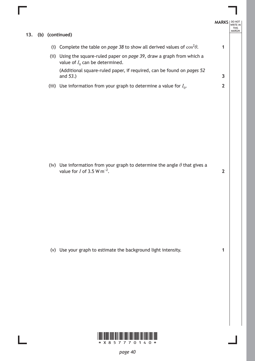
13. (b) (continued)
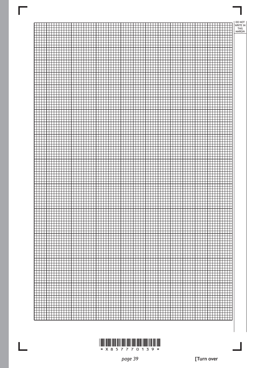
         (i) Complete the table on page 38 to show all derived values of cos²θ. 1
        (ii) Using the square-ruled paper on page 39, draw a graph from which a
           value of I₀ can be determined.
           (Additional square-ruled paper, if required, can be found on pages 52
           and 53.)                                            3

        (iii) Use information from your graph to determine a value for I₀. 2

        (iv) Use information from your graph to determine the angle θ that gives a
           value for I of 3.5 W m⁻².                           2

        (v) Use your graph to estimate the background light intensity. 1

                       *X857770140*

                              page 40
PDF page 41
Selectable page text
MARKS _{W}^{D}_{R}^{O}_{I} _{T}^{N}OT
                                                                    E IN
                                                                   THIS
                                                                  MARGIN
13. (continued)
    (c)  (i) Suggest one change to the experimental procedure that would improve
           the accuracy of measurements of light intensity.    1

        (ii) Suggest one change to the experimental procedure that would improve
           the precision of measurements of light intensity.   1

                                                      [Turn over

                       *X857770141*

                              page 41
PDF page 42
Question 14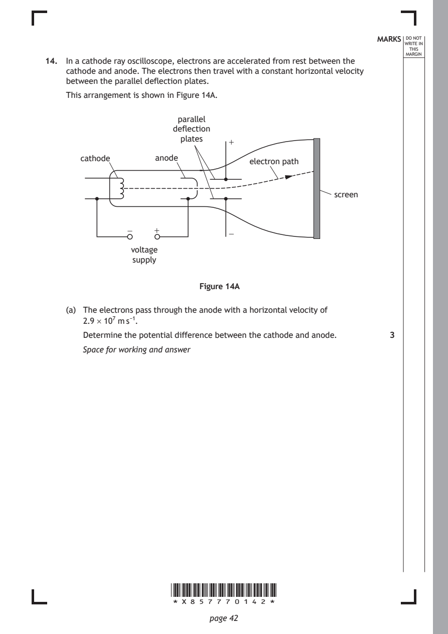
Selectable page text
MARKS _{W}^{D}_{R}^{O}_{I} _{T}^{N}OT
                                                                    E IN
                                                                   THIS
                                                                  MARGIN
14. In a cathode ray oscilloscope, electrons are accelerated from rest between the
    cathode and anode. The electrons then travel with a constant horizontal velocity
    between the parallel deflection plates.
    This arrangement is shown in Figure 14A.
                         parallel
                        deflection
                         plates
                                  +
       cathode      anode
                                      electron path

                                                     screen

               −    +
                                  −
                voltage
                supply

                             Figure 14A

    (a) The electrons pass through the anode with a horizontal velocity of
       2.9 × 10⁷ m s⁻¹.

       Determine the potential difference between the cathode and anode. 3
       Space for working and answer

                       *X857770142*

                              page 42
PDF page 43
Selectable page text
MARKS _{W}^{D}_{R}^{O}_{I} _{T}^{N}OT
                                                                    E IN
                                                                   THIS
                                                                  MARGIN
14. (continued)
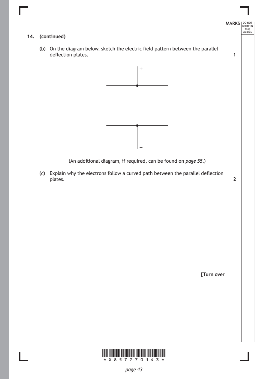
    (b) On the diagram below, sketch the electric field pattern between the parallel
       deflection plates.                                      1
                                   +

                                   −

             (An additional diagram, if required, can be found on page 55.)

    (c) Explain why the electrons follow a curved path between the parallel deflection
       plates.                                                 2

                                                      [Turn over

                       *X857770143*

                              page 43
PDF page 44
Selectable page text
MARKS _{W}^{D}_{R}^{O}_{I} _{T}^{N}OT
                                                                    E IN
                                                                   THIS
                                                                  MARGIN
14. (continued)
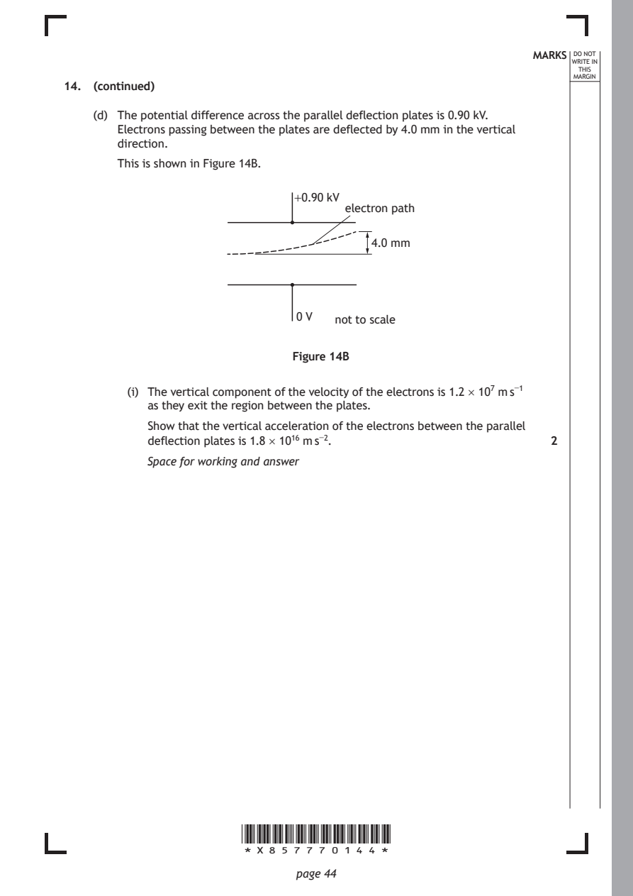
    (d) The potential difference across the parallel deflection plates is 0.90 kV.
       Electrons passing between the plates are deflected by 4.0 mm in the vertical
       direction.
       This is shown in Figure 14B.

                              +0.90 kV
                                     electron path

                                        4.0 mm

                              0 V  not to scale

                              Figure 14B

         (i) The vertical component of the velocity of the electrons is 1.2 × 10⁷ m s⁻¹
           as they exit the region between the plates.
           Show that the vertical acceleration of the electrons between the parallel

           deflection plates is 1.8 × 10¹⁶ m s⁻².              2
           Space for working and answer

                       *X857770144*

                              page 44
PDF page 45
Selectable page text
MARKS _{W}^{D}_{R}^{O}_{I} _{T}^{N}OT
                                                                    E IN
                                                                   THIS
                                                                  MARGIN
14. (d) (continued)
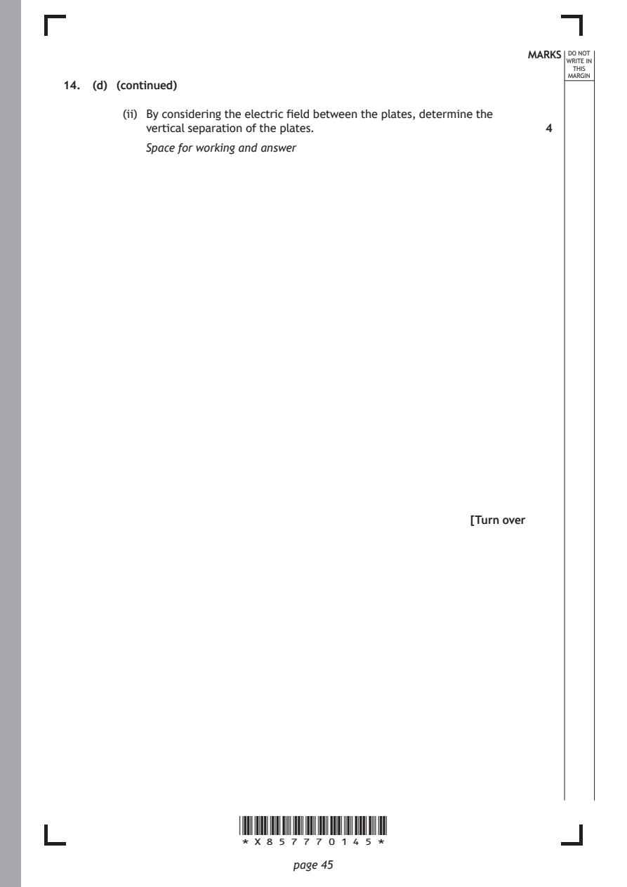
        (ii) By considering the electric field between the plates, determine the
           vertical separation of the plates.                  4
           Space for working and answer

                                                      [Turn over

                       *X857770145*

                              page 45
PDF page 46
Question 15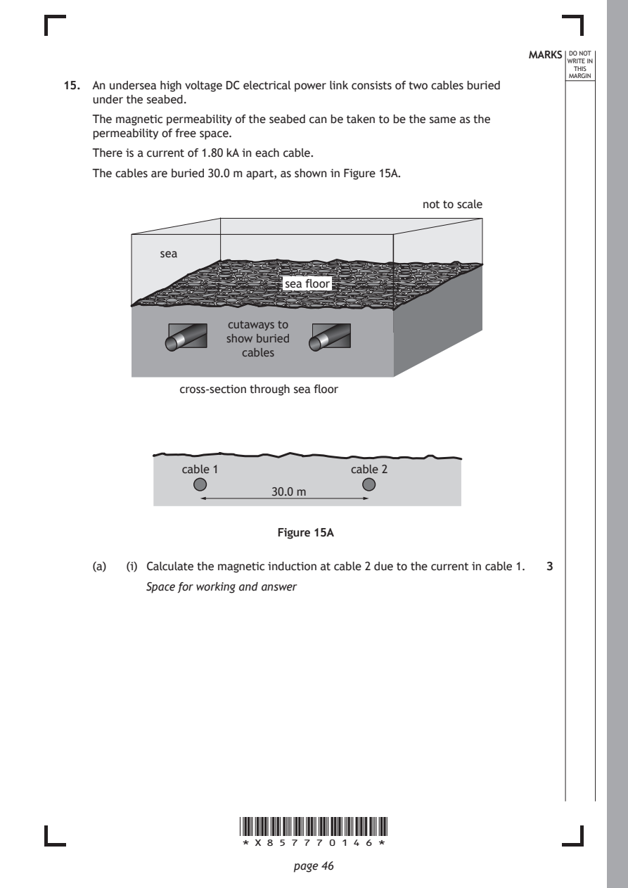
Selectable page text
MARKS _{W}^{D}_{R}^{O}_{I} _{T}^{N}OT
                                                                    E IN
                                                                   THIS
                                                                  MARGIN
15. An undersea high voltage DC electrical power link consists of two cables buried
    under the seabed.
    The magnetic permeability of the seabed can be taken to be the same as the
    permeability of free space.
    There is a current of 1.80 kA in each cable.
    The cables are buried 30.0 m apart, as shown in Figure 15A.

                                               not to scale

             sea

                             sea floor

                      cutaways to
                      show buried
                        cables

                cross-section through sea floor

                cable 1               cable 2

                            30.0 m

                            Figure 15A

    (a)  (i) Calculate the magnetic induction at cable 2 due to the current in cable 1. 3
           Space for working and answer

                       *X857770146*

                              page 46
PDF page 47
Selectable page text
MARKS _{W}^{D}_{R}^{O}_{I} _{T}^{N}OT
                                                                    E IN
                                                                   THIS
                                                                  MARGIN
15. (a) (continued)
        (ii) Determine the magnitude of the force per unit length acting on cable 2
           due to the current in cable 1.                      3
           Space for working and answer

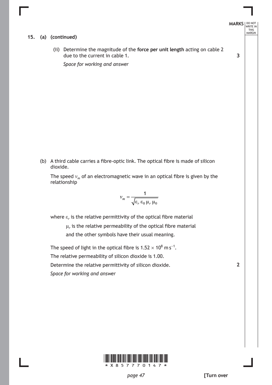
    (b) A third cable carries a fibre-optic link. The optical fibre is made of silicon
       dioxide.
       The speed vₘ of an electromagnetic wave in an optical fibre is given by the
       relationship

                                   1
                            vₘ =
                                 εᵣ ε₀μᵣμ₀

       where εᵣ is the relative permittivity of the optical fibre material

            μᵣ is the relative permeability of the optical fibre material
            and the other symbols have their usual meaning.

       The speed of light in the optical fibre is 1.52 × 10⁸ m s⁻¹.

       The relative permeability of silicon dioxide is 1.00.
       Determine the relative permittivity of silicon dioxide. 2

       Space for working and answer

                       *X857770147*

                              page 47                 [Turn over
PDF page 48
Question 16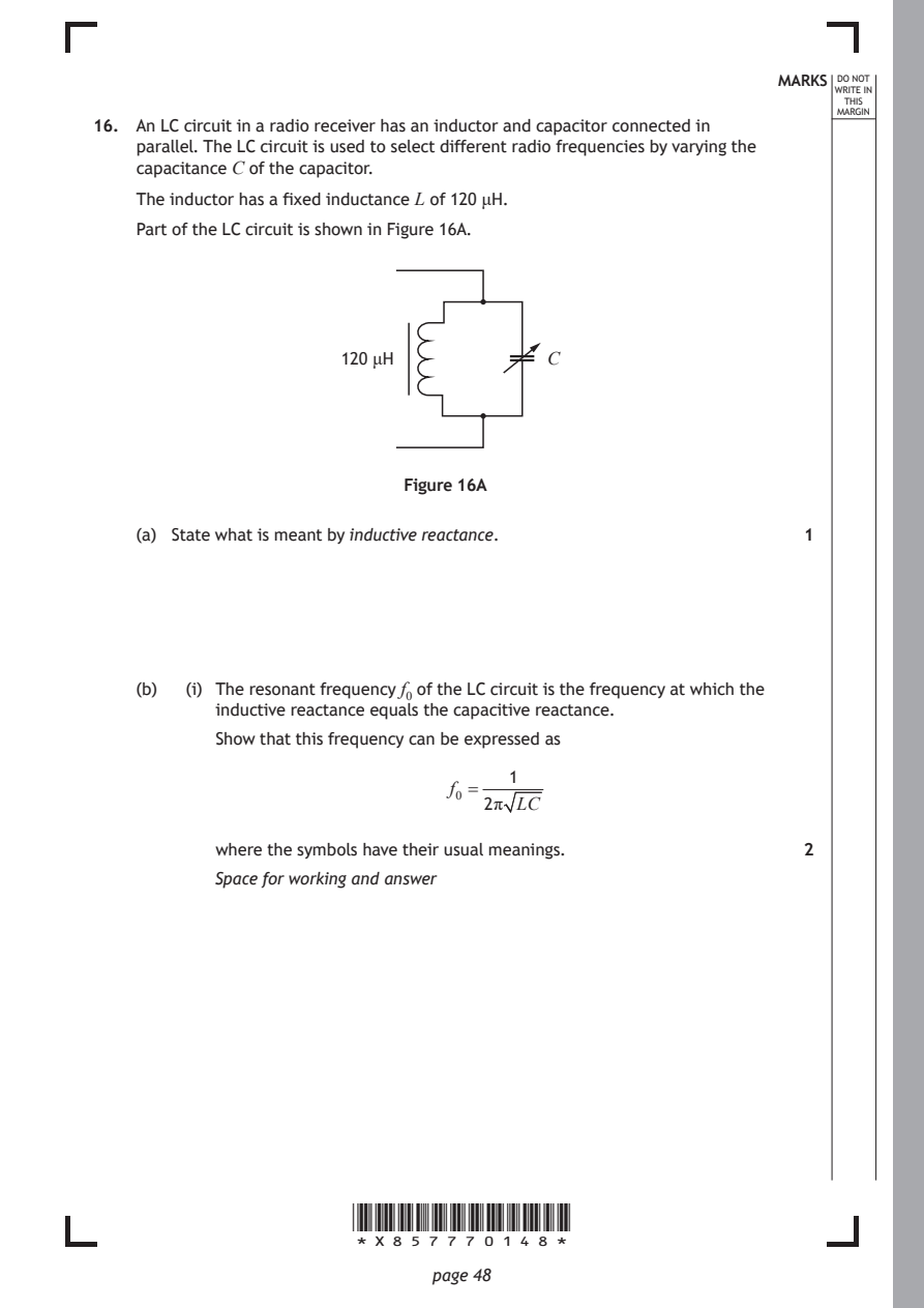
Selectable page text
MARKS _{W}^{D}_{R}^{O}_{I} _{T}^{N}OT
                                                                    E IN
                                                                   THIS
                                                                  MARGIN
16. An LC circuit in a radio receiver has an inductor and capacitor connected in
    parallel. The LC circuit is used to select different radio frequencies by varying the
    capacitance C of the capacitor.
    The inductor has a fixed inductance L of 120 μH.
    Part of the LC circuit is shown in Figure 16A.

                      120 μH             C

                            Figure 16A

    (a) State what is meant by inductive reactance.            1

    (b)  (i) The resonant frequency f₀ of the LC circuit is the frequency at which the
           inductive reactance equals the capacitive reactance.
           Show that this frequency can be expressed as

                                     1
                                f₀ =
                                   2π LC

           where the symbols have their usual meanings.        2
           Space for working and answer

                       *X857770148*

                              page 48
PDF page 49
Selectable page text
MARKS _{W}^{D}_{R}^{O}_{I} _{T}^{N}OT
                                                                    E IN
                                                                   THIS
                                                                  MARGIN
16. (b) (continued)
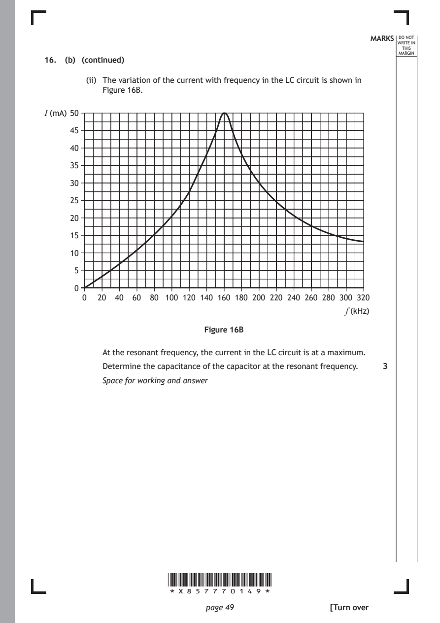
        (ii) The variation of the current with frequency in the LC circuit is shown in
           Figure 16B.
I (mA) 50

     45

     40

     35

     30

     25
     20

     15

     10

      5

      0
       0  20 40  60 80 100 120 140 160 180 200 220 240 260 280 300 320
                                                         f (kHz)

                              Figure 16B

           At the resonant frequency, the current in the LC circuit is at a maximum.

           Determine the capacitance of the capacitor at the resonant frequency. 3
           Space for working and answer

                       *X857770149*

                              page 49                 [Turn over
PDF page 50
Selectable page text
MARKS _{W}^{D}_{R}^{O}_{I} _{T}^{N}OT
                                                                    E IN
                                                                   THIS
                                                                  MARGIN
16. (continued)
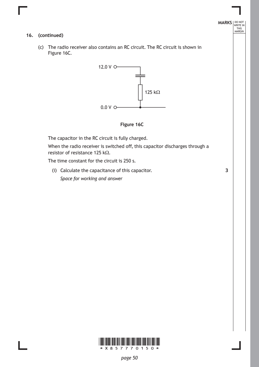
    (c) The radio receiver also contains an RC circuit. The RC circuit is shown in
       Figure 16C.
                       12.0 V

                                      125 kΩ

                        0.0 V

                              Figure 16C

       The capacitor in the RC circuit is fully charged.
       When the radio receiver is switched off, this capacitor discharges through a

       resistor of resistance 125 kΩ.
       The time constant for the circuit is 250 s.

         (i) Calculate the capacitance of this capacitor.      3
           Space for working and answer

                       *X857770150*

                              page 50
PDF page 51
Selectable page text
MARKS _{W}^{D}_{R}^{O}_{I} _{T}^{N}OT
                                                                    E IN
                                                                   THIS
                                                                  MARGIN
16. (c) (continued)
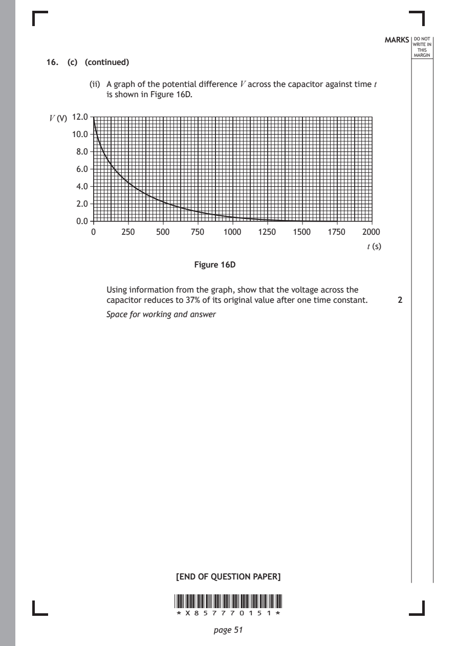
        (ii) A graph of the potential difference V across the capacitor against time t
           is shown in Figure 16D.
 V (V) 12.0

     10.0

      8.0

      6.0
      4.0

      2.0

      0.0
        0     250   500   750   1000  1250   1500  1750  2000
                                                          t (s)

                           Figure 16D

           Using information from the graph, show that the voltage across the
           capacitor reduces to 37% of its original value after one time constant. 2
           Space for working and answer

                        [END OF QUESTION PAPER]

                       *X857770151*

                              page 51
PDF page 52

Selectable page text
*X857770152*

       page 52
PDF page 53

Selectable page text
*X857770153*

       page 53
PDF page 54
Selectable page text
MARKS _{W}^{D}_{R}^{O}_{I} _{T}^{N}OT
                                                                    E IN
                                                                   THIS
                                                                  MARGIN
            ADDITIONAL SPACE FOR ANSWERS AND ROUGH WORK
Additional graph for use with question 1 (b)

         v (m s⁻¹)

               0
                                             4.1 t (s)

Additional graph for use with question 10 (c) (iii)

          a (m s⁻²)

                0
                                                t (s)

                       *X857770154*

                              page 54
PDF page 55
Selectable page text
MARKS _{W}^{D}_{R}^{O}_{I} _{T}^{N}OT
                                                                    E IN
                                                                   THIS
                                                                  MARGIN
            ADDITIONAL SPACE FOR ANSWERS AND ROUGH WORK
Additional diagram for use with question 14 (b)

                               +

                               −

                       *X857770155*

                              page 55
PDF page 56

Selectable page text
MARKS _{W}^{D}_{R}^{O}_{I} _{T}^{N}OT
                                                        E IN
                                                       THIS
                                                      MARGIN
ADDITIONAL SPACE FOR ANSWERS AND ROUGH WORK

           *X857770156*

                  page 56
PDF page 57

Selectable page text
MARKS _{W}^{D}_{R}^{O}_{I} _{T}^{N}OT
                                                        E IN
                                                       THIS
                                                      MARGIN
ADDITIONAL SPACE FOR ANSWERS AND ROUGH WORK

           *X857770157*

                  page 57
PDF page 58

Selectable page text
[BLANK PAGE]

DO NOT WRITE ON THIS PAGE

*X857770158*

       page 58
PDF page 59

Selectable page text
[BLANK PAGE]

DO NOT WRITE ON THIS PAGE

*X857770159*

       page 59
PDF page 60

Selectable page text
[BLANK PAGE]

                       DO NOT WRITE ON THIS PAGE

Acknowledgement of copyright
Question 1 pixabay.com/photos/drag-racing-dragster-racing-power-3929074
Question 2 Ekaterina Pokrovsky/shutterstock.com
Question 3 Paul Vinten/shutterstock.com
Question 5 Ad-hominem/shutterstock.com

                       *X857770160*

                              page 60